on this page and become a member of the Darling Club!


Boy,
will they be surprised this fall when classes begin and they get a taste
of Ultra-Fi
from
the Scrap Box DC Darling! (see bob.d.'s "DC Darling" schematic)
I decided
to build a "DC (direct-coupled) Darling"
since I favored this topology over the RC coupled verision at NY
Noise. Knowing that I had a pair of SE 6BQ5 output transformers
in my junk box, yanked from what I can't remember, I began the search for
the power supply magnetics
one
rainy morning in the damp basement of Fair
Radio. I selected a power transformer
which
had primary taps of 103.5, 115, and 126 VAC. The secondary B+ winding
was
rated
for 480VCT@60mA and I figured since I had several primary taps to choose
from,
how
could I miss on the B+ voltage?
As
fate would have it, I used the 103.5VAC primary to derive a B+ voltage
of 385VDC.
The
were also two 6.3VAC filament windings.
On
one, I used a full wave bridge and CRC filtration to develop 6.3VDC for
the 8532s
which
were wired in parallel and referenced to ground.
On
the other, I implemented a voltage doubler and dropping resistor to yield
12.6VDC for
the
1626s which are also wired in parallel. This filament supply was
then referenced to
+150VDC
using the cathode resistor of the 1626s.
You
see, the maximum heater to cathode voltage of the 1626 is +/-100 volts.
Therefore,
since Bob has driven the cost the 1626 up with this wonderful little Darling
(Wink!
Wink! Bob!!!), I figured I had better protect my 1626s by not exceeding
the recommend rating.
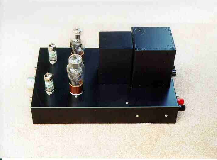
The
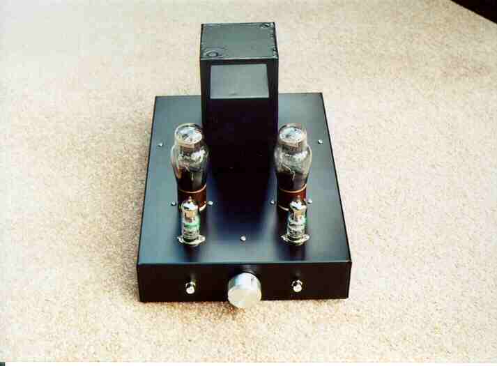
power transfomer is mounted at the back of the chassis.
The
choke, mounted just in front of the power transformer and behind the 1626s,
is the last of a bunch which I also bought surplus. It is a 2H@325mA
brute with a DCR of 50 ohms!
This,
along with the direct coupling, really makes this little Darling fast under
transient conditions.
I also used common cathode resistors and bypass capacitors for both the 8532s and 1626s, respectively. I feel this really adds to the Darling's charm and have even implemented the techique in several designs of my own.
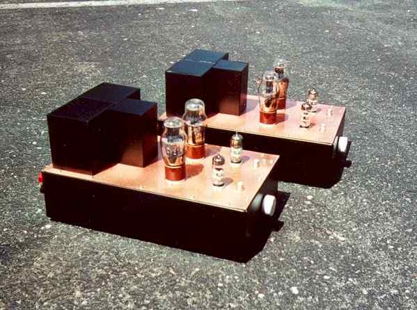
Final touches which set this Scrap Box DC Darling apart are:
(i) a 50k carbon comp audio taper volume control,
for those fast "direct-in" CD hookups on the road
(ii) a power switch, an IEC power socket, a fuse holder,
and five way binding posts on the back panel
(iii) mounting the output transformers under the chassis,
since I hate the look of open frame transformers and chokes
(iv) piece of aluminum channel stock which runs across the chassis
to reinforce the 2"x8"x12" Hammond box which the choke, in turn bolts,
to
(v) aluminum gussets in the corner of the chassis which the feet mount to.
Please
do yourself a favor! Use some of the tips and assembly techniques
on
this page and become a member of the Darling Club!

 e-mail
L.D
Moore
Return to bob.d. 's Vacuum Tube Audio Page