The Firefly 300B Monoblock Amplifier.
Introduction : The Circuit : Construction Notes
Introduction
A single-ended 300B amplifier based on the following design considerations:
- Monoblock chassis, with an external power supply.
- Reasonably compact and inexpensive.
- Aesthetically pleasing appearance.
More specifically, the circuit is designed to be partnered with a good premaplifier with low output impedance, moderate gain, and high current output. The amplifier itself doesn't have to have that much gain. Instead of the traditional circuit, running one triode as input and the other as driver, both sections are paralleled to make a more powerful driver. An input transformer makes up a some of the gain, and provides for a true balanced input connection.
I have a pair of 600:15k input transformers, rated 20 Hz - 20 kHz, made my Freed in Chicago for broadcast use. The 5x volage gain comes at a price: A 1:5 transformer like this decreases the amplifier's input impedance 25 times, and increases the input capacitance 25 times. Poor sound will result if the preamplfier isn't up to driving the resulting (very tough) load. The best approach is to use a preamplifier with a 5:1 output transformer, which is my intention. The advantage of all this work is is the ability to handle extrememly long interconnects with impunity.
Regarding the choice of driver. A minimum gain of at least 15 was needed. At the same time, though, I wanted a high current drive to avoid slew-rate limiting the output stage. Keeping with a single stage, and vetoing choke plate loads or interstage coupling mainly for reasons of excessive cost and bulk, I arrived at parallel 6CG7/6FQ7 (9 pin version of the 6SN7). This tube is linear, capable of large output swings with current and gain, and looks good too. Parallel sections result in half the output impedance and twice the current output, as well as 1/sqrt(2) less noise. Some of you may have read that parallel section tubes don't sound good. I think the problem is caused by connecting the two cathodes to a single cathode bias resistor. This forces both sections to bias away from both their ideal operating points and each other. Separate resistors allows smaller bypass caps to be used, and keeps each section biased independently.
For the record the competing topology would be to ditch the input transformer and 6CG7, and use a EL84 wired in pentode. Gain and drive in one package. It is tempting but I present I have decided to stick with triodes.
A pair of Softone RW-20 R-core output transformers was purchased direct from Shoichi Yoshimoto of Softone, Inc. These are 5k:6, with 25-40k bandwidth (-1dB) when driven by 300Bs in typical zero-feedback operation. Although the RW-20s are light on primary inductance, they are no means short on heft. Big cores like this make me happy, as does the prodigious amount of real world data provided on the web site. Most transformer companies seem obsessed with bass response, and I for one found Softone's balanced approach refreshing.
Electro-Harmonix 300B's were purchased at Triode Electronics.
Rounding out the design choices, we have AC filements and cathode bias on both the driver and output tubes. For reasons of simplicity, mostly.
The Amplifier Circuit
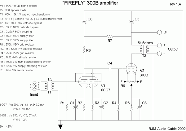
Putting it all together, we get the following circuit schematic:
Power output is about 5.8 W, input impedance 10 kohm, voltage gain 21 dB. Sensitivity for 1 W output is 200 mV RMS, 450 mV RMS to clipping. I haven't done the power supply yet. Since it is external, it is easy to switch and swap. 5 V (1.2 A), 6.3 V (600 mA) and 450 V (75 mA) is required per channel. Tube rectification and a CLC (PI) or LCLC filter is recommended on the B+.
Construction Notes
Work in progress.
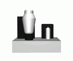
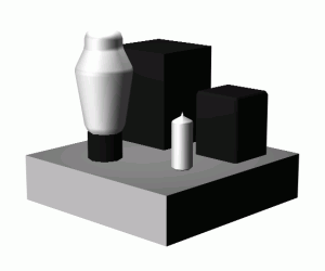
Here are the basic 5 components of the amplifier, transformers, tubes, and chassis. Inside, the signal path traces a U-shape, with the power supply feeding in through the top of the U between the transformers.


|
