The Gainclone
Introduction : Background Info : Construction Notes
Introduction
The model 4706 Gaincard from 47 Laboratories is a 25 Watt stereo amplifier about the size of a video cassette, powered by a large external supply. It amplifier uses a power op-amp and a minimum of parts, connected with the shortest possible signal path, particularly the feedback loop. Background info:
Junji Kimura's Gaincard held the fascination of many, especially within the DIY community. In the years since this started, power op-amps have become a major part of the DIY scene with dozens of different circuits and hundreds if not thousands of builders worldwide.
- Power opamp IC DIY found can be had at the Chip Amps forum at diyAudio.com
This page dates back to the beginning when the Gaincard was literally a black box. The non-inverting circuit shown here is, for better and for worse, the most faithful rendition of the original Gaincard possible given what was then publicly known about it.
Background Information
Some things we know for sure:
From the 47 Labs website:
- World's smallest number of parts - 9 parts per channel ( excluding attenuators )
- World's shortest signal pass length - 32 mm ( including the length of parts )
- World's shortest NFB loop length - 9 mm ( including the length of the resistor )
- World's smallest filter/condenser - 1000µF, (50 W version - 2200µF)
- Powerful voltage regulation with high capacity transformer - 170 VA cut-core transformer ±individual coils
- Dual mono construction with each channel in a separate chassis.
- Rigid and compact aluminum chassis construction to release vibrations smoothly.
- Separate 12-position attenuators for each channel.
- Can be up-graded into a pair of complete mono amplifiers by adding another Model 4700 Power Humpty.
From reviews:
- Gain = 27dB (22x) [Listener] or 30dB (32x) [Stereophile]
- Input impedance = 22 kohms [47 Labs] or 15-35k variable [Stereophile]
- Circuit is non-inverting, output impedance is less than 0.1 ohm.
- Attenuator is ladder type. (From stereophile Zin data.)
Other details remain off the official record to this day:
- Power cord is captive four pin molex, one per channel.
- Mute switch is a mechanical switch of the output.
- Carbon resistors are used throughout.
- LM3875 chip is used.
- Four FE5D diodes are used for rectification.
The rest is a simple matter of deduction. The data sheets for the LM3875 and its smaller cousin the LM1875 are very informative.
LM3875 product folder and LM 3875 .pdf datasheet.
LM1875 product folder and LM 1875 .pdf datasheet.
Typical operation, from the LM1875 datasheet:
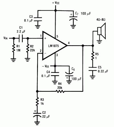
Please note that I will be using the component numbering used here throughout this page, so refer back to this diagram as needed.
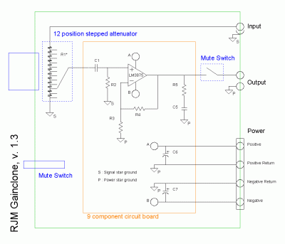
It is understood that Kimura removed the film bypass caps C3 and C4, and R1 on the circuit will be replaced by the stepped attenuator. C2 is most likely also omitted. This gives the stated nine part circuit. To be consistant with what is known about the Gaincard C6 and C7 should be increased to 1000 µF, and R3 reduced to about 680 ohms, and finally the LM1875 replaced with the bigger, better performing cousin LM3875. This result is shown below:
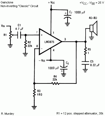
Grounding is critical. The output signal must not share any of the inverting input ground path. I recommend a binary star ground as follows: Two ground points are defined, the base of R2 is the signal ground S and the base of R3 the power ground P. Attach all the S grounds together, and all the P grounds together, and then connect the two grounds by a single wire. (Note: The RCA input ground can go to the base of the attenuator, rather than R2.) The case can be left floating or attached to the signal ground. The chips should be well heatsinked, but electrically isolated from the heatsink. An isolated version of the LM3875 exists (LM3875TF) which makes this easy to do.
The actual layout of the circuit board could be something like this:
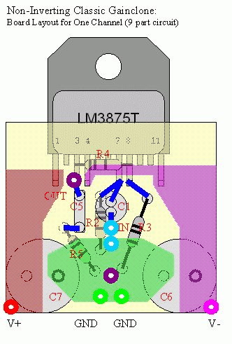
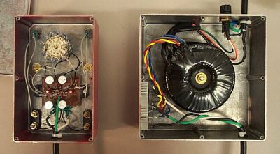
It may look ugly at first, but its really very smart and compact. R4 is soldered directly between the leads of the IC, which is itself tucked underneath the board together with R2 and R5. All the capacitors and R3 are on the top side. All the unused pins are cut off except for pin 11 which is kept for mechanical stability.
Suggested components: (All resistors 1/4 W carbon film, R4 can be 1/4 W or 1/8 W and is soldered directly accross the leads of the LM3875.)
| R1 | ** | C1 | 4.7 µF / 50V Black Gate N series |
| R2 | 22k | C5 | 0.22 µF / 63V WIMA MKS |
| R3 | 680R | C6 | 1000 µF / 25V United Chemicon LXV or similar low impedance type |
| R4 | 22k | C7 | 1000 µF / 25V United Chemicon LXV or similar low impedance type |
| R5 | 1R | U1 | LM3875T |
| ** 12 step ladder attenuator, use 22k, 4k7, 2k2, 1k5, 1k, 680R, 470R, 330R, 220R, 150R, 68R, 33R. A 50 kOhm volume potentiometer could be substituted. | |||
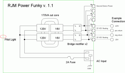
The power supply is very simple. Transformer, diodes only. There are no filter capacitors. The transformer should be rated to around 150-300 VA and be either a torroid, R-core or C-core type with dual secondary windings of 16 VAC. This will provide 25 wpc with LM3875s. 12 or 15 VAC secondaries can also be used successfully. Diodes should be rated to at least 5A. I prefer two bridge rectifiers, but one bridge or 4 individual soft recovery diodes can be substituted. Use a 0.5 or 1 A fuse. Separate power supplies can be used for each channel if desired.
The following is a suggested layout-schematic for the power supply:
Construction Notes
I started by setting up a prototype using the LM1875 chip with regular EI laminated transformers. The transformers hummed and so did the amplfier outputs. I never got the combination to work cleanly.
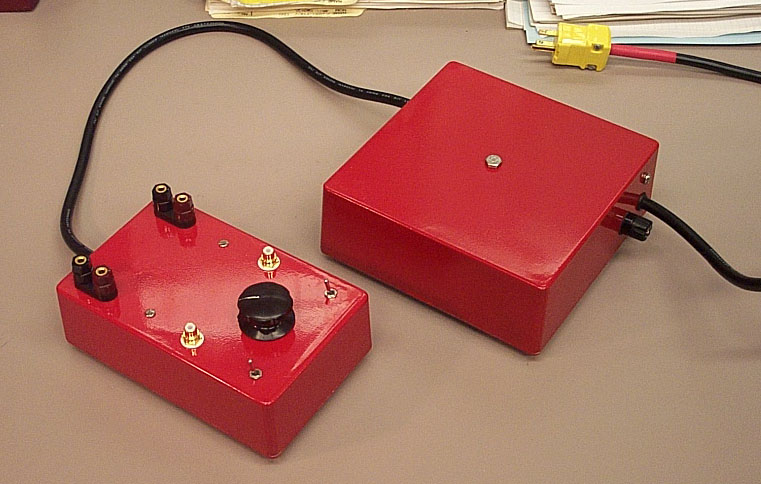
The next build used the LM3875 chip. Both the amplifier and external power supply were cased in Hammond 1590 series cast aluminum boxes. A 160 VA torroid with 2x 12 V secondaries and electrostatic screen from Plitron supplied the power. Dual bridge rectifiers as shown above.
C1 should be included to protect your speakers but can be omitted if you know your source components are not DC coupled at the output. After comparing a 4.7 µF Black Gate N series to a piece of straight wire, I preferred the sound with the Black Gate in and recommend this part without hesitation. Note that C1 must be non-polar.
If you do it right the amplifier is completely quiet but grounding can be a problem.
I followed the Gaincard pretty closely in using the mute switches, the attenuator, and choosing to have the same gain and input impedance. I also have pretty much the same short length of signal path and feedback loop, the latter obtained by soldering R4 directly across the chip leads.
I used carbon film resistors for R2-R4, metal film for R1, and metal oxide for R5. I conclude from my experiences that carbon film is the right choice for the R2-R4, AB carbon composition sounded too noisy and fuzzy, metal oxide too grainy, and (from a different circuit) metal film too, uh, metallic and zingy. For R1 and R5 I'm not sure. In general, though, the capacitors affected the sound more than the resistors, the diodes more than the capacitors, and the transformer most of all.
For a given capacitance, a lower voltage power supply gives a softer, more relaxed sound. Generally, the lower the impedance of your speakers, the lower the voltage should be. In any event for 1000 µF capacitors and 4 ohm speakers I liked 12 V secondaries (±17 VDC) the best, but it might be a little too soft for some people. 15 or 16 VAC should be fine for just about everyone.
I tried replacing my two 50A bridge rectifiers with 4 discrete diodes. I tried both Shottky and ultrafast types, rated 3 or 5 amps. I preferred the two big bridges, which sounded more open and powerful, but clearly there is room to experiment. Soft recovery types are probably the best bet.
This amplifier is compact, looks great, sounds great, has a few dozen clean watts per channel, and dissipates only 2.5 W idle. Total parts cost is less than $200, even if you have to buy the case and transformer. And its its an easy (and safe) project to build. In short, no excuses. Build one today!
rjm003.geo at yahoo.com

|
