Pack 471's Computerized
PINEWOOD DERBY FINISH LINE DETECTOR
Important notice:
As of March 1, 2001, I am no longer able to give technical support for the construction of this track finish line detector. The material furnished on this page is supplied as is with no technical support.
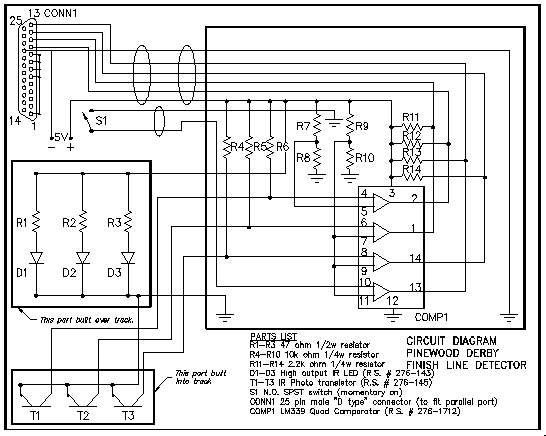
The following is an electronic schematic and parts list for the items needed to construct an infrared detector for the finish line of a Pinewood Derby racetrack utilizing an external power supply and the parallel port of an IBM compatible computer of at least 486/33Mhz running DOS 3.1 or better. Also included is a narration concerning the construction of the detector as well as the BASIC code required to operate the detector.

PARTS LIST
|
R1-R3 |
47 ohm 1/2 w. resistor |
|
R4-R10 |
10k ohm 1/4 w. resistor |
|
R11-R14 |
2.2k ohm 1/4 w. resistor |
|
R15-R16 |
10K ohm 1/4 w. resistor |
|
D1-D3 |
High output IR LED (Radio Shack # 276-143) |
|
T1-T3 |
IR Photo transistor (Radio Shack # 276-145) |
|
S1 |
N.O. SPST switch (momentary on) |
|
Conn 1 |
25 pin male "D type" connector (for parallel port) |
|
Comp 1 |
LM339 Quad Comparator (Radio Shack # 276-1712) |
CONSTRUCTION NOTES
The unit I constructed was done in two parts. The Electronics Box, (The dash marked area on the right side of the schematic) and the detector, (lower left side of schematic.)
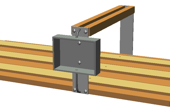
The detector was constructed in two parts. First, a piece of 3/4" x 2" x 12" Pine was used for the top of the detector. A 3/4" wide by 3/8" deep channel was dadoed out of the wood. Holes were then drilled for the IR diodes spaced the same as the lanes on the track. The dadoed channels were also used to route the wires and resistors R1-R3. We then drilled corresponding holes in the center of each lane at the finish line of the track with the IR phototransistors mounted on the bottom in a similarly dadoed channel. Metal brackets attached the top frame to the track, and the IR diode emitters mounted to the top of the frame. The distance between the IR diodes and IR transistors on our detector was about 5 1/2 inches. This left about 5 inches net clearance for the racecars. Make sure that you have enough clearance for your tallest racer to pass through the frame after it is mounted to the track.

After the wiring was completely installed in the detector frame, I cut thin plastic strips (plastic rain gutter material) and attached the strips with screws to the outside of the frame. These strips covered the dadoed channels of the frame. This gave a "finished" look to the project and also covers and protects the wiring and IR diodes etc.
The electronics can be constructed using a printed circuit board, or simple point-to-point wiring. Layout is not critical. I enclosed the electronics in a small box, and then attached the box to the side of the detector on one of the metal brackets. We then had a single cable routed to the computer. We used instrument wire to connect between the computer and the electronic box, and also between the electronic box and the detector.
Start Switch S1 can be any type of "momentary on" SPST switch that can be attached to the start handle of the racetrack. As the handle was tipped down, the switch made contact and then opened after the handle was released.
![]()
The following is the code to run the detector through a parallel port. This program will work better if compiled into an executable program with something like Quick Basic. Scale is the approximate scale of the Pinewood Derby cars (1:25). Length is the length in feet of the Pinewood Derby track. These numbers are used for the scale miles per hour calculations. The number 889 in this program is the decimal equivalent of the printer port address plus 1. This may have to be changed to match the address of other computer's printer ports.
'screen header & mph factor calculation
50 SCREEN 9: COLOR 15, 5
A$ = " "
OPEN "PRN" FOR RANDOM ACCESS READ AS #1
LOCATE 4, 10: PRINT "THIS PROGRAM WILL NOT FUNCTION PROPERLY WITHOUT THE FINISH "
LOCATE 5, 10: PRINT "LINE DETECTOR PLUGGED INTO THE PRINTER PORT."
LOCATE 7, 10: INPUT "Equipment test? (y/n) ", ans$
IF UCASE$(ans$) = "Y" THEN GOSUB 7000
IF A$ = CHR$(27) THEN GOTO 50
LOCATE 10, 1: LINE INPUT "ENTER SCREEN HEADING (38 CHARACTERS MAX) -"; SCREEN$
LG = LEN(SCREEN$)
IF LG > 38 THEN CLS : GOTO 50
SCALE$ = "25"
LENGTH$ = "32"
LENGTH = VAL(LENGTH$): SCALE = VAL(SCALE$)
MF = ((LENGTH / 5280) * 3600) * SCALE
'opening screen
SCREEN 7
LOCATE 3, (((40 - LG) / 2) + 1): PRINT SCREEN$
100 ONE = 0: TWO = 0: THREE = 0: RESTORE
C = 0
COLOR 14, 5
LOCATE 18, 36: PRINT " "
LOCATE 6, 6: PRINT "LANE 1"
LOCATE 6, 14: PRINT "LANE 2"
LOCATE 6, 22: PRINT "LANE 3"
LINE (33, 59)-(85, 139), 14, BF
LINE (97, 59)-(149, 139), 14, BF
LINE (161, 59)-(213, 139), 14, BF
LOCATE 20, 36: PRINT "SEC."
LOCATE 22, 36: PRINT "AVG."
LOCATE 23, 36: PRINT "MPH"
LOCATE 20, 1: PRINT " "
LOCATE 23, 1: PRINT " "
'wait for start line switch activation
51 start = INP(889)
LOCATE 2, 1
PRINT start AND 16
IF (start AND 16) = 0 THEN GOTO 200
A$ = INKEY$
IF A$ = "Q" OR A$ = "q" THEN GOSUB 6000
GOTO 51
'start timer and wait for finish line activations
200 TS = TIMER
210 T0 = TIMER - TS
A$ = INKEY$
IF (INP(889) AND 64) = 0 THEN GOSUB 1000
IF (NOT (INP(889)) AND 128) <> 128 THEN GOSUB 2000
IF (INP(889) AND 32) <> 32 THEN GOSUB 3000
IF A$ = CHR$(27) THEN 100
IF T0 > 99 THEN LOCATE 18, 36: PRINT " ": GOTO 250
LOCATE 18, 36: PRINT INT(T0)
250 GOTO 210
'screen output
1000 T1 = TIMER - TS
IF T1 < 1 THEN RETURN
IF ONE = 1 THEN RETURN
READ CO, C
LINE (34, 60)-(84, 138), CO, BF
LOCATE 13, 7: PRINT C
LOCATE 20, 5: PRINT USING "##.####"; T1
LOCATE 23, 6: PRINT USING "###"; MF / T1
ONE = 1
RETURN
2000 T2 = TIMER - TS
IF TWO = 1 THEN RETURN
READ CO, C
LINE (98, 60)-(148, 138), CO, BF
LOCATE 13, 15: PRINT C
LOCATE 20, 13: PRINT USING "##.####"; T2
LOCATE 23, 14: PRINT USING "###"; MF / T2
TWO = 1
RETURN
3000 T3 = TIMER - TS
IF THREE = 1 THEN RETURN
READ CO, C
LINE (162, 60)-(212, 138), CO, BF
LOCATE 13, 23: PRINT C
LOCATE 20, 21: PRINT USING "##.####"; T3
LOCATE 23, 22: PRINT USING "###"; MF / T3
THREE = 1
RETURN
DATA 1,1,4,2,15,3,2,4
6000 LOCATE 23, 2: LINE INPUT "DO YOU WANT TO QUIT ? (Y OR N) "; Y$
IF Y$ = "Y" OR Y$ = "y" THEN SYSTEM
IF Y$ <> "Y" OR Y$ <> "y" THEN LOCATE 23, 2: PRINT " "
RETURN
7000 CLS 'TEST ROUTINE FOR PRINTER PORT
7001 LOCATE 2, 2: PRINT "Press ESCAPE to exit"
A$ = INKEY$
IF A$ = CHR$(27) THEN RETURN
IF NOT INP(889) AND 64 = 64 OR A$ = "1" THEN GOSUB 10000
IF INP(889) AND 64 = 64 OR A$ = "1" THEN GOSUB 10500
IF NOT INP(889) AND 128 = 128 OR A$ = "2" THEN GOSUB 11000
IF INP(889) AND 128 = 128 OR A$ = "2" THEN GOSUB 11500
IF NOT INP(889) AND 32 = 32 OR A$ = "3" THEN GOSUB 12000
IF INP(889) AND 32 = 32 OR A$ = "3" THEN GOSUB 12500
IF NOT INP(889) AND 16 = 16 OR A$ = "8" THEN GOSUB 13000
IF INP(889) AND 16 = 16 OR A$ = "8" THEN GOSUB 13500
GOTO 7001
10000 LOCATE 12, 20:
PRINT "Track 1 Detected"
RETURN
10500 LOCATE 12, 20:
PRINT "Track 1 Ready "
RETURN
11000 LOCATE 14, 20:
PRINT "Track 2 Detected"
RETURN
11500 LOCATE 14, 20:
PRINT "Track 2 Ready "
RETURN
12000 LOCATE 16, 20:
PRINT "Track 3 Detected"
RETURN
12500 LOCATE 16, 20:
PRINT "Track 3 Ready "
RETURN
13000 LOCATE 18, 20:
PRINT "Start Switch Activated"
RETURN
13500 LOCATE 18, 20:
PRINT "Start Switch Ready "
RETURN
SUB FILLBOX1
LINE (34, 60)-(84, 138)
END SUB
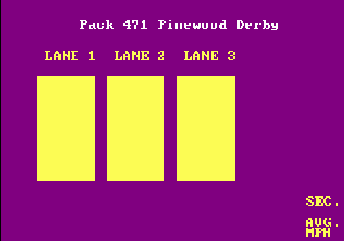
The screen produced by the above code will look similar to this prior to the start of a race:

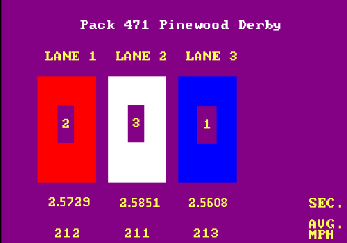
After the race, this is what the screen would look like showing lane 3 as the winner, lane 1 as second place and lane 2 as third place
 :
:
Many thanks go out to Tom A. for his programming skills to modify this to work on our computer, Tom E. for his donations of materials, Gary G. for his help in construction of the track, and Larry DeBoer of Tyler, MN, whose original program was published on the web several years ago but changed to work with only three lanes and a parallel port instead of a game port.