Version 2.3
01 january 2002
by
Aart Jochem

Through this page I like to share my experience and findings as beginning robot amateur. I had much help myself by browsing other peoples' pages and I used hardware and software made available on the net by their designers (thanks Marvin Green, Karl Lunt, Motorola and many others!). Maybe my approach, tips or software inspire others. That's what Internet is all about: INSPIRATION!
Content:
- Projects
- Tips on building the BOTBoard
- Software I have made in SBASIC
- Useful links
Projects
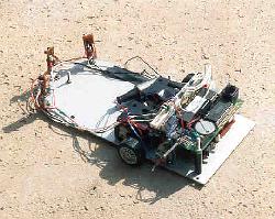
MAR.A: Tattletale based mobile robot
 In
my first project I used an old OnSet Tattletale 4 processor board. This board, based on a MCU with BASIC-interpreter
in ROM had 16 I/O-ports and 8 analog ports. The project had to be very
low budget. I used simple infrared detection (photo) to measure distance to obstacles
in the range very near to infinity in 5 steps. I used a simple 3-bit D/A-converter and H-bridge
with discrete components to drive 2 DC-motors with plastic gears I took
from 2 toy cars of $5 each. The cheap motors wrecked the project. They
used huge amounts of power and delivered hardly any torque. The plastic gearboxes
had dead positions and the Bot couldn't pull the weight of extra batteries
for the power consumption of the motors. The Tattletale couldn't work in
multitasking or something like that, what I needed for my plans of modeling
behaviors parallel (like subsumtion). This and lack of time made me stop
hobbying on robots.
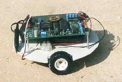
MAR.B: BOTboard based robot
 I
got anxious to start a new project after a short study of Intelligent Agents.
I read the book of Joseph Jones and Anita Flynn, which made me decide that
the MC68HC11 was it: low cost and very versatile. I bought Marvin Green's
BOTboard2 and I happened to build it flawless the first time. Now I use
Karl Lunts SBASIC and PCBUG11. I have been exercising on the different functions
of the MC68HC11 (see software section ) and build the platform and driver circuit. Next sensors were added: first bumpers, then light sensors and next is IR-obstacle detection.
I
got anxious to start a new project after a short study of Intelligent Agents.
I read the book of Joseph Jones and Anita Flynn, which made me decide that
the MC68HC11 was it: low cost and very versatile. I bought Marvin Green's
BOTboard2 and I happened to build it flawless the first time. Now I use
Karl Lunts SBASIC and PCBUG11. I have been exercising on the different functions
of the MC68HC11 (see software section ) and build the platform and driver circuit. Next sensors were added: first bumpers, then light sensors and next is IR-obstacle detection.
BOTboard Tips
Building BOTBoard2
Building the BOTBoard2 requires no special skills. Just be very precise if you build the board. Debugging hardware may take a lot of time and frustration. Equipment to debug hardware is very costly and often you have to do with only a DVM. Use it to check for short circuits between pins while you build. Be sure to avoid these short circuits by using a fine tip on your soldering iron. First cut the leads before soldering components to avoid strain on the PCB, place IC's in sockets after all soldering has been done to avoid heat damage. Be aware of the risk of static electricity. Building will take more time, but the chances of building it right the first time are much higher
Getting the components
For me it was hard to obtain the MC68HC11A1FN. All electronic stores are ´specialized´ in PC-hardware. I had a congress in Korea but even in the Yongsan Electronic Market with 2500 electronic stores I couldn't succeed. At last HEC in Delft (NL) helped me out for fl. 24,- ($12). The reset chip DS1233 was as hard to get, but I could not wait any longer, so I relied on the RC-circuit in the reset line to power up smoothly, and it worked. The rest of the components are wide available. I used a 5 cells of a spare NiCad powerpack of a cordless drillmachine as power supply. It delivers 6 volts, 2 Ah, enough to have lang operating times.
Update: I found the DS1233
at Farnell,
but it got overheated when I tested it. I will come back on this...
Update 2: After recharging my NiCad cells, the supply voltage reached 6.8 volts. The MAX232 is the only chip that requires 5 vols with a max. of 6 and blew out. I replaced it, but next time it will go again. Beter use the MAX231 next, which can handle up to 13 volts.
First tests
I use the program environment Marvin prepared. Be sure to update the SBASIC version to version 2.7, to avoid a hidden feature when you start programming interrupts. The cable connecting the PC to the BOTBoard should be a strait RS-232 cable and not a null-modem cable. Check with your DVM that pins 2 and 3 are not crossed. The LED is strapped to PD3 on BOTBoard2. Use this LED for debugging if you have no other means. I used a wire with a connector on jumper block J3 as probe to test the state of other outputs. When you use the LED on PD3 first disable the SPI by writing the spcr register. See SBASIC code below.
            include "regs11.lib"
            main:
            pokeb spcr,  $07	'disable SPI function
            pokeb ddrd,  $0008	'PD3 is set for output
            pokeb portd, $0008	'LED is on
            end
Motors
I found 2 cheap servo motors (Fl. 22,-, $12 each) at Conrad Electronics. A servomotor combines a DC-motor, a plastic gear and driver electronics in one housing at a relative low price. An unmodified servo cannot turn continuously, but can move over 180-270 degrees. Modifying is easy: open the case, cut away the notch in the gearhead, saw the axis off the potentiometer and position it in the mid-position and re-assemble the servo et voila, the servo is a controlled DC-motor. Karl Lunt eleborates on this subject, as did several others on the net.

Sensors
My approach is to navigate with IR-sensors for object avoidance and light sensors for goal identification (for instance a charging station with a bulb). But the bottom line is that if IR-detection fails (the legs of a chair) the robot must be able to detect a collision. So I started with the basics: bumpers. I used several constructions with mixed success. The problem is to make a robust construction and still detect small touches with objects. I used switches, which needed too much force to make contact and whiskers, which deformed after a number of hits with objects. Finally I ran into the simple but repeatable whisker construction of Dennis Clark. I have two whiskers in front and one at the backside, which are sensitive and robust (see photo left). They are constructed with a small piece of circuit board, some solder pins and 1.1 mm piano wire. It is amazing what simple whiskers can add to the behavior of the robot. A simple wall following routine made my family for the first time enthusiast! (though for myself I will never forget the moment that I succeeded in switching the LED on and off :-).
UPDATE: MAR.B has seen the light! I added 2 photo-resistors and connected them to AD-ports 2 and 4. I used shielded wire to connect them, because in my attempts to make good bumpers I learned that the motors generate a great deal of distortion on the analogue signal. A simple light following routine using the MC68HC11's analogue to digital conversion abilities added another behavior to the bot. Documentation will follow soon.
Next on my to-do list is the IR-sensor (based on Siemens SFH5110 for object detection.
Software
The following files are SBASIC-programs I used to test the BOTBoard and to try the different aspects of the MC68HC11. I put them here as an example. I tried interrupts, the timer system and some routines to operate the bot.
- testbot2.bas: just blinks the LED, a first test
- testsnd.bas: test the soundfunction
- intsnd2.bas: use TOC2-interrupt to generate a 500 Hz tone
- testserv.bas: test the servoport S2, with modified servo attached
- rti-test.bas: test the real time interrupt
- follight.bas: follow the light (with sound) test the real time interrupt
- events.v01.bas: operate the servo's based on an defined agenda. Events based on sensory input and on a planned agenda is the thought behind this program, but for now only actuators are invoked. I'm still working on sensors.This is my current work.
Useful links
- Marvin Green's PARTS-page, the designer of the BOTBoard and BOTBoard 2
- Karl Lunt's page, the author of helpfull tools, as SBASIC
- Motorola's HC11 Programmers Reference Guide
- MIT's 6270 ftp page
- A usefull BOTboard beginners page at the Seattle Robotics Society
- The Tao of Programming, the source of all programs (134 kb pdf)


