A number of experiments to establish how the RS-485 network works.
This experiment does not use a PIC! It verifies that the RS-485 line can be used to communicate the action of a push-button switch to an LED. When the button is pressed the LED lights and when the button is released the LED dims (or vice-versa). This is done very simply by hooking the TX enable to the button and the LED to the RX with the A and B lines looping back from the transmitter onto the receiver.
The proposed circuit diagram for the this is:
The breadboard looked like this:
See the video. Back to top of page.
The simple RS-485 transmitter continually transmits messages that can be interpretted by the RS-485 Listener with 3 LEDs and the RS-485 Transceiver with 3 LEDs and Push Button. The messages are broadcast messages.
Six different messages are sent:
The nibble is: 0 0 0 1
Which becomes the packet: 0 0 0 0 0 0 0 0 0 1 0 1 1 0 1
The bit sequence to send is: 0 0 0 0 0 1 0 0 (0x04) 0 0 1 0 1 1 0 1 (0x2D)
The nibble is: 0 0 1 0
Which becomes the packet: 0 0 0 0 0 0 0 0 1 0 1 1 1 1 1
The bit sequence to send is: 0 0 0 0 0 1 0 0 (0x04) 0 1 0 1 1 1 1 1 (0x5F)
The nibble is: 0 0 1 1
Which becomes the packet: 0 0 0 0 0 0 0 0 1 1 0 1 1 1 1
The bit sequence to send is: 0 0 0 0 0 1 0 0 (0x04) 0 1 1 0 1 1 1 1 (0x6F)
The nibble is: 1 0 0 1
Which becomes the packet: 0 0 0 0 0 0 1 0 0 1 0 0 1 0 1
The bit sequence to send is: 0 0 0 0 0 1 0 1 (0x05) 0 0 1 0 0 1 0 1 (0x25)
The nibble is: 1 0 1 0
Which becomes the packet: 0 0 0 0 0 0 1 0 1 0 1 0 1 1 1
The bit sequence to send is: 0 0 0 0 0 1 0 1 (0x05) 0 1 0 1 0 1 1 1 (0x57)
The nibble is: 1 0 1 1
Which becomes the packet: 0 0 0 0 0 0 1 0 1 1 0 0 1 1 1
The bit sequence to send is: 0 0 0 0 0 1 0 1 (0x05) 0 1 1 0 0 1 1 1 (0x67)
The proposed circuit diagram for the Transmitter is:
The breadboard looked like this:
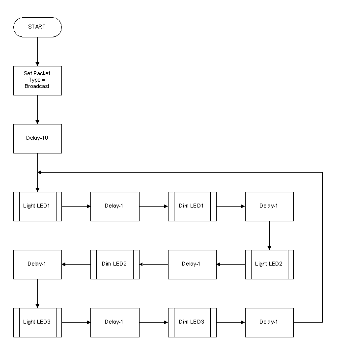
A flow diagram of the Transmitter is:

The Transmitter is a simple 2 byte process. It has 2 file registers for the data to send, a file resister for bit count and a file register to indicate complete and if on second byte.
Which message to transmit is decoded from an array of messages to send. The message is then built and sent to the transmitter by setting the appropriate file registers. There are flags to indicate if:
There is a file register to indicate the number of nibbles to transmit. There is an array of 8 file registers (16 nibbles) set aside as the transmit buffer.
After transmitting the message there is a programmed delay.
Download the source code and a compiled hex file. See the video. Back to top of page.
The state of the LEDs is controlled by messages received over the RS-485 line.
The proposed circuit diagram for the Listener is:
The breadboard looked like this:
Download the source code and a compiled hex file. See the video. Back to top of page.
This is effectively module C01.