This RS-485 is a multipoint network using half-duplex. The following diagram illustrates this:

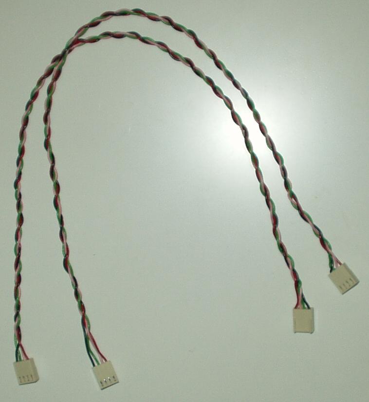
The cabling is 4-wire (2x twisted pairs). One pair is the differential A and B data lines, the other pair is the power (12V unregulated / 0V). The 0V line is the common ground for the entire network segment. The 12V provides limited power to devices on the network, should they need it, and must be regulated down to +5V at the point of consumption. The network should source a maximum of 1A, because the cable wiring is only 7/0.2.
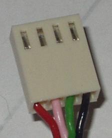
The colour scheme adopted for the cables is: RED = +12V, PINK = data A, GREEN = data B, and BLACK = 0V (ground).
Here are a couple of the shorter cables, and a close-up of a connector:


RS-485 experiments done to learn about the implmentatation techniques.
The network consists of an RS485 Customer [C01] board at each point, an RS485 board [B05] and (possibly) 2 teriminator boards (one of these boards can supply the power to the network). The initial state of a board is to be in receive mode.
Each customer board sets up to receive and uses the timer interrupt every 58µs (this interrupt interval is configurable in software). Each timer interrupt represents a 'phase' flip, either +ve or -ve. This phase is constantly 'flipping' with each interrupt. Transmission starts at the start of the +ve phase. The network is listened to by the receivers at the start of the -ve phase. A receiver has the entire cycle to detect the bit, but the 'receiver' timer interrupt can be 'synchronised' by using an interrupt on the data pin. After it has synchronised this interrupt is no longer needed. If this drifts until reliable communication is not guareenteed, it will drift back over time.
There are 2 types of terminator board, powered and un-powered. The un-powered terminator board [T02] puts a resistance load over the RS485 data lines A and B of 120 ohms. Line termination is needed to alleviate signal echoes reflecting back down the A and B lines which is a problem for longer data runs. The powered terminator board [T01] does the same as the un-powered terminator board but it additionally supplies power (at least 12V) to the power lines, and it biases the data lines.
The B05 board communicates with the C01 boards listening to and responding to packets. The indivual C01 boards can also communicate with each other.
The protocol defines the structure of the packets transmitted on the bus.
The 'idle' state of an RS485 network is deemed to be a logic 1 (HIGH). This is implemented with the biasing introduced by the T01 terminator board.
When A is more +ve than B, this is considered a logic 0, and when B is more +ve than A, this is considered a logic 1. This needs to be verified as it depends on what actually happens and what is supposed to happen.
To transmit a logic 0, the driver pulls the B data line down. This has the effect of making A more +ve than B which a receiver will see as a logic 0. To transmit a logic 1, the driver tristates to 'not driving' and the biasing makes the line B more +ve than A which a receiver will see as a logic 1. The PIC transmits by enabling and disabling the driver. By doing things this way the reciever can still be polled and checked and only 2 pins of the PIC are used. If the received bit is an 0 when the transmitted bit is a 1, then a collision has occurred and the PIC ceases transmission of the packet.
The receiver continuously records all data sent on the bus. It automatically performs the error check. It is immune to bus collisions; they only affect transmission. The transmission Error Check is compared with the receiver Error Check to ensure a packet has been transmitted properly. A sequence of 6 or more like bits indicates an error and the packet is discarded, and the error condition remains until 6 consecutive 1 (High) bits is subsequently detected indicating an idle line, as described in the protocol.
The convention for bit order adopted is 'left off, right on'! So for the nibble 0xD which has a binary pattern of 1101, the bits are transmitted in the order 1 then 1 then 0 then 1. This translates as most-significant-bit first.