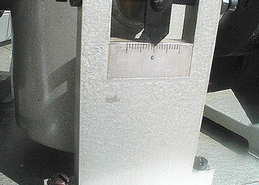
990605-007a
Centering guide aluminum bracket. On the upper
part is the mass lock-in screws, which will be shown with more clarity
on other views.
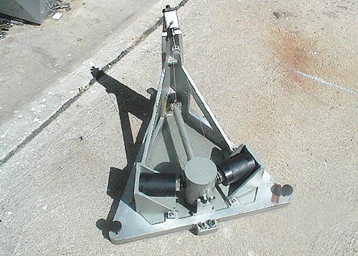
990605-008a
Another frontal view of the seismometer. The
black round objects are the alnico magnet assemblys, for each of the two
coils (one for damping, one for signal). They can be moved in position
not only from the supporting brackets, but, the magnets themselves allow
for some positioning via bolts....they are really 3 pieces, not counting
the bold hardware.
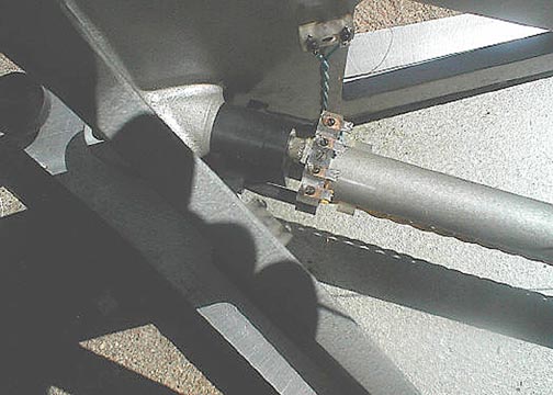
990605-009a
This is the worst part to show with any clarity.
The boom comes from the right to center, and it has two prongs which fit
in dimples of another plate whose only attachment is via a stiff wire,
which is connected to a post from the mass. One can see some of the
signal and damping wires bridging the boom and mast terminals.
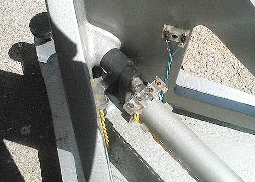
990605-010a
Another view of the boom pivot area.
See
John Lahr's almost equivalent pivot, 990521-062c, & 64c, 2rd and 4th
from the top of page
With this Sprengnether pivot, one can disconnect the
bridging signal and damping coil wires, and move or take out the boom/mast,
and re-insert with little difficulty. On John Lahr's, pivot, one
would have to disconnect the torsion wire and/or other parts to work on
the boom/mass.
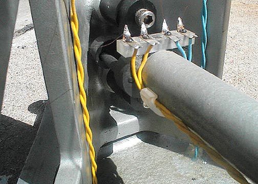
990605-011a
Another view of the pivot area. The boom diameter
seems quite large, and it is....but very sturdy. Since those days,
the boom weight versus the mass weight should be greatly reduced to enhance
the signal.
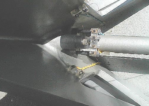
990605-012a
Another view of the pivot area. Here one can
see some more of the bridging wires. Again, the only contact is one
stiff torsion wire between the boom and the mast.