

A generator is a device that converts mechanical energy into electrical energy. The electric potential is produced from one or more coils of wire cutting through a magnetic field. When a wire cuts through a magnetic field, a voltage is induced in the wire. If a conductor cuts through 108 flux lines (magnetic force lines) in one second, one volt is produced. In generators more than one turn of wire is usually used. 100 turns of wire would produce 100 times more power than one turn of wire. And multiple coils of wire may also be used. Also to increase the power output of the generator, stronger magnets could be used (more magnetic lines for the conductor to cut), and the speed of the conductors cutting the magnetic lines could be increased. This way the conductors will cut through more lines of flux per second.


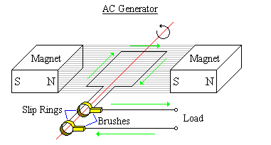
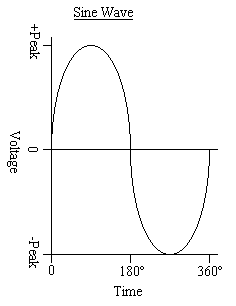
A simple diagram of an AC generator, also called an alternator, is shown above. The alternator consists of a coil of wire called the armature that rotates in a magnetic field. Because the armature needs to spin, slip rings are connected to the armature that make electrical contact to a pair of brushes. And the armature is turning in the magnetic field, so it is constantly cutting the lines of magnetic flux in a different angle, and therefore it produces a wave form, called a sine wave, that is always changing in voltage and polarity.
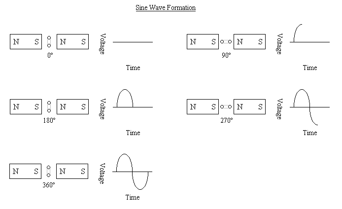
When a conductor cuts through lines of magnetic flux, the angle at which the conductor cuts through them will determine the voltage induced in the conductor. If it cuts through the lines of flux at 90° the most possible flux lines are cut in the amount of time it takes for the conductor to pass through them. And at 0°, parallel to the lines of flux, no lines of flux are cut, so no voltage is induced. The voltage induced in a conductor at a certain angle is  . E is the voltage induced in the conductor at that time, EMAX is the maximum voltage induced in the conductor (maximum voltage of the output wave), and q is the angle the wire is cutting through the flux. The figure below shows the formation of the sine wave in an alternator.
To find any voltage currently induced in a wire the formula is  . E is the voltage induced in the wire, F is the flux from the magnets, q is the angle the wire is cutting through the flux, and t is the time in seconds for it to pass through.
The polarity of the current in the conductor can be found by the left hand rule. Extend your fingers in the direction of the magnetic field (north to south, so point your fingers to the south), and keep your thumb at 90° to your fingers, and have your palm facing the armature. When the wire moves toward your palm, your thumb will be pointing the direction of current flow in the wire (given that current flows - to +).
Because the sine wave is constantly changing voltage and polarity, a sine wave that has a peak output of 10 volts does not have equivalent power to 10 volts of direct current through the same load. It only has about 70.7% the same power. To convert the peak voltage of a sine wave to the effective value (the equivalent power of a sine wave to a DC voltage, also known as root mean square, or RMS value), multiply the peak voltage by 0.707 (the reciprocal of the square root of 2). Or if you need to know the peak voltage of a sine wave, multiply the RMS value by 1.414 (the square root of two). The same formulas work for current.
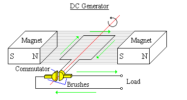
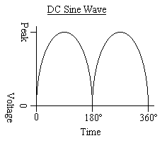
A simple diagram of a DC generator and its output is shown above. It is similar to the AC generator, but in place of slip rings it uses a commutator. The commutator acts somewhat like a switch, and whenever the polarity is about to change, it switches brushes, so the polarity stays the same. This is mechanical rectification, and using a bridge on an alternator will get the same effect. The same formulas to find the RMS and peak value of an AC sine wave are used for the DC wave form.
One major disadvantage of the alternator is that the high voltages and currents produced in the armature must be connected to the external load via some form sliding contacts like slip rings and brushes. This causes sparks and arcing, and wears down the slip rings and brushes. For that reason some generators have stationary coils of wire, called stator windings, which generate their power from a moving magnetic field from rotor windings. Although the rotor will need contacts of some kind, it only needs to have sufficient power to provide a strong magnetic field.
The generators shown above are only single phase generators. This means there is only one coil of wire. A two phase generator has two coils of wire 90° apart. Thus the two coils have outputs that are 90° out of phase. And in a three phase generator, three coils are put 120° apart from one another. This then creates three outputs that are 120° out of phase. The outputs can be put into series or used separately.
The number of cycles per second is called the frequency. The measurement is called hertz (Hz), but before 1967 it was called cycles per second (cps). In America, the household power is 60Hz. This means in one second, 60 alternations occurred. And the radio station you listen to might be in the MHz, which represents megahertz, or millions of cycles per second. And KHz is kilohertz, thousands of cycles per second, GHz is gigahertz, billions of cycles per second, etc.
You may have also heard of different frequencies as having different wavelengths. This is the peak positive to the next peak positive (or negative to negative) length, if the wave
is traveling at the speed of light (186,000 miles per second, 300,000,000 metres per second). The wavelength can be found by the following formulas:
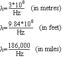
l represents the wavelength. To find the wavelength of a wave in some other measurement, just divide the speed of light in that measurement by the frequency of the wave.