Thermoelectric modules work because of a property called the Peltier effect. That is, when a current flows through two dissimilar conductors the junction between the two conductors will either absorb or release heat, depending on the direction of current flow. In a thermoelectric module, Bismuth Telluride pellets are soldered to usually copper on opposite sides of the pellet. The junction occurs between the Bismuth Telluride and the copper.
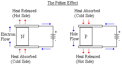
Shown below is a simple diagram of how a Peltier device works. The Bismuth Telluride pellet can be doped to become P or N-type. When a current runs through the pellet, the heat will go in the direction of the carrier flow in the pellet. In an N-type pellet, the carriers are electrons, and in a P-type they are holes (spaces where there is no electron). If you look at the N-type pellet below, the electrons in the pellet are repelled by the negative charge of the battery, and attracted to the positive, so the electrons in the pellet move up along with the heat. The same goes for the P-type pellet, except it is the holes that carry along the heat.

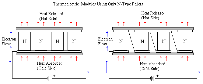
In a thermoelectric module many P and N-type pellets are used so that the module can pump more heat. Although it is possible to make a module out of only one type of pellet, it is not practical. In the diagram below there are two modules using only N-type pellets. In the first diagram the pellets are connected electrically and thermally in parallel. Although this design does work well, the power supply will need to be a low voltage supply but at a very high current. A typical sized module might need to supply one volt or less at a few hundred or even thousand amperes.
In the next module, the pellets are placed electrically in series and thermally in parallel. While this does solve the power supply problem, the diagonal connections between the pellets provide a path for heat to flow, thus decreasing performance and efficiency.

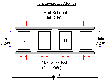
In order to correct all problems a combination of P and N-type pellets are used. In the configuration below the pellets are connected electrically in series, while thermally in parallel without providing a good conductive path for the heat. In the N-type pellets electrons in the pellet (carriers) are repelled by the negative charge of the battery, and move towards the positive side. At the same time, the holes in the P-type pellets are repelled by the positive side of the battery, and move towards the negative. Because of their arrangement the carriers in both types of pellets move in the same direction.

Although there are P and N-types of semiconducting materials, there is no junction between them. The only junctions are between the copper and a pellet, therefore thermoelectric modules do not have a depletion region, and do not act like a diode. So thermoelectric modules may be connected to a power supply in either direction, but changing polarity will change the direction of current flow, thus the direction of carrier and heat flow, so the hot and cold sides will switch around.
To hold everything together ceramic substrates are used because of their electrical resistance, thermal conductivity, and strength. Although because of the thermal stress on Peltier devices, they are usually not made much larger than two inches (five centimeters).
Thermoelectric modules are often used as cooling devices for semiconductors, like microprocessors, where the cool side is placed on the semiconductor and the hot side to a heat sink and fan. They can also be used to heat things, or even generate power. When generating power, one side is heated while the other cooled. When the heat flows through the device it moves the carriers in the pellets, generating an electric potential.