The description of damage of each seismic resisting system is a generic type of damage that pertains to some level of earthquake input energy that allows the seismic resisting system to go beyond yeilding and into the inelastic range.
|
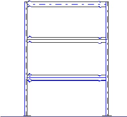
MOMENT FRAME DAMAGE |
Expected structural damage of Moment frames Systems in Steel
Moment frames are an inherited high
interstory drift system. Considerable nonstructural damage will occur. Depending the stiffness of the moment frame and the inelastic properties, the interstory drift will be in the 1" or 2" to 3" range for a 15-foot story. This is high and the exterior
facade as well as the interior partitions will be severely damaged. There will be structural damage also. It wasn't a surprise that many moment frames welded joints were damaged in the Northridge earthquake. But now that we are trying to fix the welded joints, has anyone ever seen what a beam looks like at the plastic hinge after a few cycles. There is severe distortion of the flanges with possible tearing of the web to flange connection. I still do not know how to fix the beam except to remove the whole beam and this will cost a bundle. It may be easier to provide a very large number of welded joints using small beam sections with a similar pre-Northridge joint detail. I am assuming that some of the welds will fail but not all of them and that the remaining welds are adequate to prevent the building from collapsing. It may be cheaper to fix a welded joints than replacing the entire beam. This is one concept but I still think this is not the right direction. Owners should be told up front about the expected damage by using a moment frame system. The building will be a total lost in the long run. An appropriate solution to minimize the inelastic damage of moment frames is to have a backup energy dissipation system that absorbs the energy before the moment frame beams goes inelastic.
|
| All sketches were done using Autodesk Autocad LT saving as .dxf
files. the files were opened up with Paint Shop Pro size and reviewed and then saved as a .gif file. In the future these sketches will be saved as .dwf files and review by you with
Java programs, such as, Autodesk Whip or Cadviewer light. |
|
Expected Structural damage of Eccentric Brace Frames
The structural damage will be concentrated at the link beam. The floor slab will be severely cracked up due to the movement of the link beam. In addition, any nonstructural elements at or near the link beam, such as, partitions, etc., will be severely damaged. It is recommended that any exit facilities, stairs or exit access not be located at the link beams. Exit doorways will be frozen shut and the occupants will not be able to escape after an earthquake. If EBF is located at the exterior facade, the exterior should not be attached to the link beam at all. Some additional framing should be added to bypass the link beam. The reason for not attaching the exterior facade to the link beam is
that there will be such large beam rotations the exterior connections will be severely damaged causing the facade to fail and fall. The link beam will have the same type of damage as the moment frame, i.e., severe beam flange rotation and possible tearing of the flange to web connection at the point of the plastic hinge. The result will be that the link beams will have to be replaced. This operation will require the removal of the brace, floor, and link beam or some similar work. |
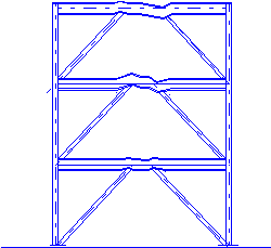 EBF DAMAGE |
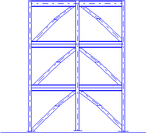 CBF
DAMAGE |
Expected structural damage of Concentric Braced frames
Buckling of the compression braces in the CBF will occur in large or great earthquakes. The result is the tension braces will absorb the additional seismic forces beyond the buckling load.
There are three points in the compression brace where the buckling will occur and is dependent on the connection to the gusset plate. If the brace to connection plate with a
hinging mechanism, then one bucking point may exist and that is at the mid-length of the brace. The columns of a CBF shall always be larger enough not to buckle at all and the anchorage at the base shall be able to resist the maximum possible tension load. Therefore, the repair of a CBF after a large or great earthquake should only be replacing the buckled braces. To minimize repair cost, the original designer should provide easy access to the braces for easy removal and replacement. Even though CBF is a stiff system, the interstory drift will be significant enough when considering all the inelastic displacements of each component of the CBF system that the exterior facade should be articulated. The interstory drift of a braced frame system should be in the 1" to 1 1/2" range. This kind of drift will cause damage to the facade and the interior partitions.
|
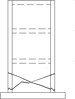 CONCRETE SHEAR WALL DAMAGE
|
Expected structural damage of Concrete shear walls
No matter what, concrete shear walls will crack up. The larger the earthquake the more cracks that will occur and the size of the cracks will be larger. Under cyclic axial loads from
overturning moments, the concrete in the boundary element will degrade. Confinement ties will keep the concrete from blowing out, but removal of the concrete may be required. The tension steel will yield leaving the permanent deformation or cracks in the boundry element.
|
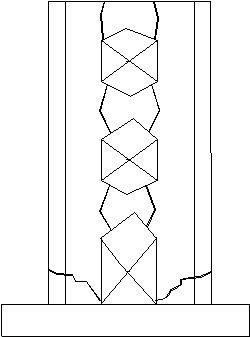 COUPLED
SHEAR WALL DAMAGE |
Expected structural damage of Coupled Concrete Shear Walls
Like concrete shear walls, Coupled concrete shear walls will crack up. The exterior boundary elements will degrade from the high vertical axial loads. The coupling beams will crack and in some cases, chunks of concrete will fall. It is recommended to enclose the coupling beam with chicken wire to keep the concrete from falling. Somewhat vertical cracks will occur at the coupling beam ends due to the yielding of the tensile diagonal bars. refer to my home page for schmatic representive of coupled shear walls.
|
 BASE ISOLATED DAMAGE |
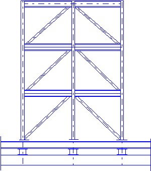
Expected structural damage of an base isolated building
There is very minimal structural damage in a base isolated building because the primarily structural system will not yield. In addition, the lateral displacements above the
isolators will be very low which will minimize the non-structural damage in the facade and partitions. Also the accelerations will be low which will reduce the demand on the anchorage of other non-structural and structural elements. There is some potential
structural damage only if the isolators fail and the building lands hard on the secondary support system. In general, the overall additional cost of the base isolated system will
negate the post earthquake repair cost.
|
|
Disclaimer
All information, opinions, comments, etc, expressed on this web page are this structural engineer's professional opinions, comments, etc. and are not intended to harm any other engineer's
professional opinion, comments, buildings or projects.
|
|
DRAWING NOTES
All graphics are cartoon representation of structural damage of seismic systems, actual damage will occur and vary from what is shown.
The intent of this page is to show damage at certain levels of capacities, i.e., concrete shear wall at 10 times the square root of f ' c, etc.. I would appreciate E-mailing me photos or web sites locations of damage in the seismic resisting elements during tests. The purpose of this is for web site readers who are not structural engineers to review damage of such elements. As for the structural engineers,
they should research the test data that has been done over the years and should show their architect clients and building owners these test results. Do not wait until after the next earthquake and their attorneys are knocking on your door to show them the potential damage of the seismic systems that you neglected to tell them.
|
 Click on spinning ball for more
Seismic Resisting Systems damage
|
|
AL WHITECAR
STRUCTURAL ENGINEER |
| SEISMIC RESISTING SYSTEM DAMAGE |
| DRAWN BY AL WHITECAR |
| MARCH 1999 |
S-4 |

