|

|
A PERSONAL WEBSITE AND PROFESSIONAL RESUME'
| SEISMIC RESISTING SYSTEMS PAGE 2 |
|

CONCRETE MOMENT FRAMES |
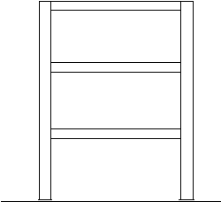
CONCRETE MOMENT FRAMES Concrete moment frames are the same as steel moment frames which are flexible lateral elements, such that, the expected nonstructural damage may be intolerable to the building owner. Concrete construction is a monolithic construction process which means the engineer should not pick and choose which elements are the lateral elements. All elements of monolithic constuction (in the building) will be part of the lateral load systems and the engineer cannot play God and pick and choose which ones. Non-frame columns and horizontal floor members will rotate with the story drift yeilding bending and shear stresses in both members. Always consider that in a large or great earthquake that the moment frames will go into the inelastic range. Therefore, the moment frame will be pushed further and the corresponding drift will be quite huge. If The moment frames are too flexible then there is the possibility of collapse or partial collaspe. With concrete moment frames, the drift calculations shall consider the fully cracked concrete column sections and concrete beam sections. This is a conservative approach to the drift calculation. The beam poperties may be stiffer due to the presence of compression reinforcing. An engineer should always consider strong column and weak column configurations and P-delta effects. |
||
|
BEARING WALL SYSTEMS
The most common seismic resisting system used for most buildings is the bearing wall/shear wall. These walls can be built using the following materials;
Each of these type of bearing wall systems have unique seismic characteristics. |
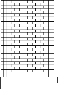
Unreinforced Masonry Walls Unreinforced masonry and stone bearing wall systems are not appropriate as seismic resisting system in seismic zones three and four. They are very brittle elements with little or no ductility. The problem is that they were built back in days when brick and stone was the state of the art an structural engineers and architects did not know better. Today they have become are favorites of preservatists and architects who don't know better. Seismic upgrading these old relics is always a challenge. There is always out-of-plane anchorage of the wall to the diaphragm and out-of-plane effects of the wall fascia elements. (Peeling away of the exterior brick layer). There is the low limited shear capacity and the limited overturning shear capacity, i.e., rocking shear of the pier or wall. But the most critical shear is the cracking shear, this is the overturning shear in the wall or pier that tension is develop and damaging cracks occur. This is sometimes very low level where unsightly cracks will lead to a reg tag. |
||

TILT-UP CONCRETE WALLS |
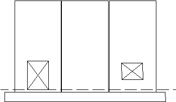
Precast Panels or Tilt-up Wall Panels Many large warehouses, commercial buildings, and retail discount buildings are built using tilt-up construction. Typically, this type of construction consists of prefabricated wall panels that are lifted into place. These walls are very tall, some can be 30 feet or more in height. In addition, many of these walls are perforated with many openings for doors and windows and in many cases these wall panels are erected as individual wall elements not attached to the next panel. Because of these reasons, their seismic performance in large earthquakes is questionable. Due to the fabrication of the tilt-up panels, they do not have adequate overturning capacity required for both tension and compression from overturning moments. Although, proper detailing of the interface between the panels will solve this condition, but may buildings are still erected with no attachment between panels. The anchorage of the wall panels to the roof or floor diaphragms is another major problem with their seismic performance. A tilt-up building tends to pull away from the diaphragm causing localized collapse of the roof or floor. Thus, the tilt-up building becomes a tilt-down building. Furthermore, many tilt-up building have bare minimum reinforcing at the interface of the walls and foundation and/or slab on grade which means they can slide. Another problem with buildings using tilt-up construction is they tend to be quite huge with little or no interior lateral elements. These buildings rely on the roof diaphragm to span between the exterior walls which means high diaphragm shears and displacements. This is a prescription for disaster. |
||

MASONRY SHEAR WALLS |
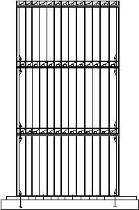
Reinforced Masonry Walls Reinforced masonry shear walls do not have the same seismic strengths as reinforced concrete walls. This is due to the method of construction. Masonry construction is not a homogenous material, masonry wall is composed of masonry, mortar and grout. The strength of the masonry wall is the bond between the reinforcing and the grout and the grout itself. The masonry element, such as, a concrete masonry unit is only a form for the grout. Take away the masonry unit, the volume of shear wall is quite small. Therefore, the masonry walls have to be quite long and numerous. The result will be rigid structure with little energy dissipation other than for cracking of the masonry walls. |
||
 WOOD SHEAR WALL |
Wood Shear Walls Used in most wood frame construction, wood shear walls are usually consist of plywood or a waste wood products such as OSB etc. Some engineers will use the gyp board walls as shear walls, others will use the stucco or plaster walls as shear walls. Neither of these walls will provide the ductility needed in seismic country. These low ductility walls will be severely damaged in a large or great earthquake. The following components that make up a wood shear wall is the sheathing, nailing, anchors and hold downs. But the most important item is the ability to get the lateral load into the wall. A good engineer should follow the shear transfer from the roof to the ground using the appropriate connectors to transfer the shear. The problem with wood construction is that wood shrinks and many connectors tend to loosen up. This leaves a lateral system with a unique damping system. But it also leaves a building with larger drifts that will damage the other non shear walls and non structural elements. A good wood frame design is to provide for many shear wall lines and collector lines especially in a multi-level building. It becomes very difficult to provide adequate shear transfer over the height of the shear wall. An example is the shear transfer at the second floor may be quite huge verses the roof level and the number of nails needed will split the wood. |
||
| Disclaimer All information, opinions, comments, etc, expressed on this web page are this structural engineer's professional opinions, comments, etc. and are not intended to harm any other engineer's professional opinion, comments, buildings or projects. | |||
|
|
AL WHITECAR
|
||
| SEISMIC RESISTING SYSTEMS PAGE 2 | |||
| DRAWN BY AL WHITECAR | |||
| Copyright Al Whitecar structural engineer 1999, free graphic images obtained from many sites thanks | MARCH 1999 | S-3A | |