“PLL” Programming
PROJECT
I had the need to test a frequency
synthesizer design that had the controller separate. So the end result was to
use a BASIC STAMP 2 ( as recommended by a RF engineer ) that would program the
PLL. The PLL I needed to use was National Semiconductor’s “LMX2316”. The
LMX2316 is “MICROWIRE” programmable with a maximum frequency of 1.2GHz. This
project was in the iDEN band so we actually had 3 frequencies we needed to
generate. The two NOT discussed here were in the 700MHz band and its
application is proprietary. The 56MHz signal is used throughout a system that
is doing upconversion and downconversion of these iDEN band frequencies. I had
an old copy of National Semiconductor’s “CODELOADER” software that would help
you figure out what values to program into the PLL depending on your
configuration.
** DOWNLOAD THE BASIC STAMP 2 FIRMWARE: “LMX2316_56.BS2” (saved in Notepad)
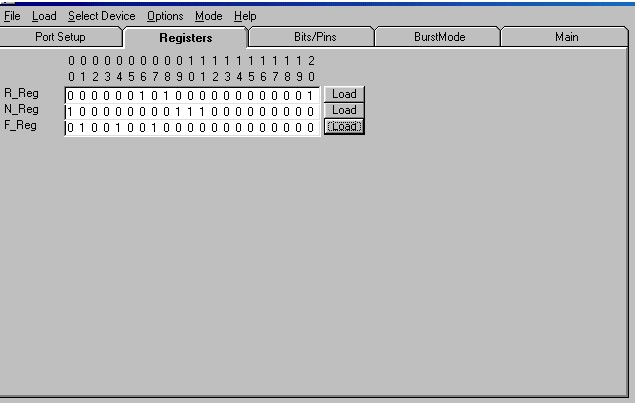
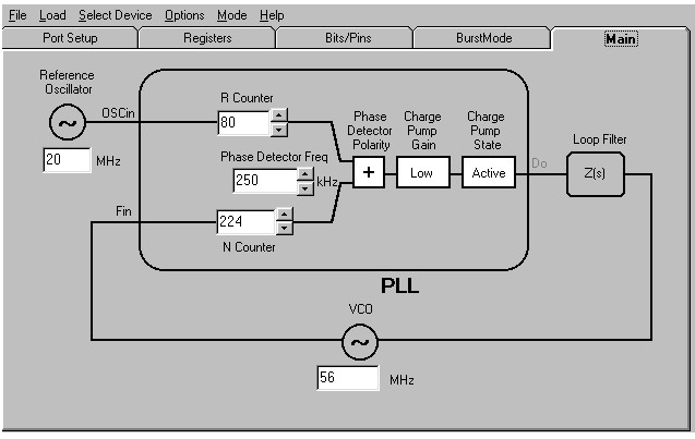
Here are some screen shots from
CODELOADER:
FIG. 1 - Register settings
to be programmed into the LMX2316.

FIG. 2 – Main functional diagram of PLL in
its operating environment.

I can’t discuss the hardware setup
in detail (as in part numbers) but I can give you a little bit that might help
you out. My reference oscillator was 20MHz and phase detector frequency was
250kHz. I would recommend placing a 3RD order low pass filter at the
output of the PLL but as close to the VCO as possible. You want a filter with a
small bandwidth (at the output frequency of the PLL) to help reduce any spurs
that may have been created from the PLL. If you see harmonics with a 250kHz
spacing from your main signal, then you have a problem.
Overall the BASIC STAMP 2 worked
like a champ. I had no problems and the development time was very fast.
PARALLAX has a very nice product on the market, but I am sure you already know
that!
 steevn.geo@yahoo.com
Page operating since 03/10/2003
This page hosted by
 Back to Projects Page