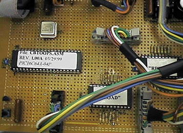

"CBT": Circuit Breaker Tray
This was my first "real" project using a PIC microcontroller. We have a rack system that deals with high votage (-48VDC) and high current. This system (used in a base station) comes with a pretty complicated circuit breaker and wiring assembly that was a real pain to test by hand. I got stuck testing the protoypes by hand (with a continuity tester and about 12 "D" sized prints. Each tray took me about 25 minutes to test this way. I decided to whip up a test fixture that would test everything for me. It took me a total of 4 weeks to write the code, debug it, design the hardware (real hard huh!) and build the prototype. Overall I was very pleased with myself. After completeing the test fixture, test time went from 25 minutes each to a little under 2 minutes. This fixture will tell the fault ("OPEN" or "SHORT") as well as the location of the fault.
Specs:
The overall operation of the circuit is simple. I use a DS1233 to monitor the MCU and reset it in case of a brownout or if I want to manually reset it. I made sure the display I used was compatible with the LCDs I usually use. The VFD I used is pin for pin compatible with the "STANLEY" 2X20 LCD I use. This way if I have a problem with the VFD I can replace it easier. Basically I set a pin high and check to make sure that the other pins are either low or high depending on what they should be. I used the PIC16C64A and the 2.4576MHz TTL canned OSC because that's what I had on hand. Click here to see the schematic. The overall design may not be the "best", but I designed it when I first started using MCUs on a regular basis. So if you see something that SHOULD NOT be done that way, don't hesitate to voice your opinion. Afterall, I'm still learning and want to design the best that I can.


 Back to Projects Page
or go back to my
Microcontroller page.
Web Site last updated:09/28/99
Page operating since: 09/28/99
If you have any questions please contact me at:
steevn.geo@yahoo.com