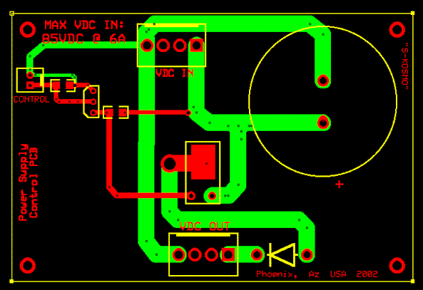
Ä DC Power Supply Switch Ä
PROJECT
This
project uses a BS170 (N-Channel Enhancement
Mode FET) and a IRFU9120N (P-Channel HEXFET
Power MOSFET) to control the DC source. The ON / OFF action is controlled by
placing either a TTL LOW or a TTL HIGH on
the “GATE” of the BS170. The MR751 diode is
used to protect the circuitry.
** The
schematic is available in .PDF here.
** The
PCB layout is available in .PCB (EXPRESS PCB) here.

I
used this circuit on two different projects where we wanted to control the DC
power (+50V @ 4A MAX) to an automated test system via the PC. I wrote the
software in AGILENT VEE to control the power up
/ power down of the test rack. I laid out the PCB’s using ExpressPCB, cost me
US$62.00 (for QTY of 3) and had them in 3 days! Overall this circuit works
well.
 steevn.geo@yahoo.com
Page operating since 09/10/2002
This page hosted by
 Back to Projects Page