
Spherical Mirrors/Parabolic mirror/Rigid Parabola/Shallow Parabola/
Deep Parabola/Asymmetrical Parabola
Being a pioneering design, this type of cooker has seen maximum variations, Besides, the design offers several advantages. One of the most important is that the mode of cooking is very much identical to day to day cooking. There are two major types of concentrator solar cookers: (I) cookers which concentrate the light from below, and (ii) cookers which concentrate the light from above.
Heat coming from below is most convenient for routine cooking, hence, many designers have concentrated on this type of cookers. There are a lot of designs in this category, and they are classified on the basis of the type of reflectors used (I) Spherical reflector (S), (ii) Parabolic reflectors (P), (iii) Fresnel types (F), (iv) Cylindro parabolic (CP), and (v) Mirrors plane (MP).
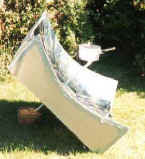
Spherical mirrors are the simplest type of reflectors, very easy to build and use. Focusssing sun rays are also easy, and if one opts for a moving vessel to meet the focus, cooking can also be done very easily. Such a design was suggested for the first time in the year 1961 by Stam (1961) (Type S1, Figure 1). He suggested a large reflector of 4.0 m diameter made of local material which could even include mud, and the reflector surface suitably smoothed with fine mud/cement and coated with aluminized polyester. An appropriate technology handbook describes a simple method of construction of the spherical mirror in the ground (a tall tripod with a long string to which a stone is attached at the tip, will act as a guide for excavating a hollow in the ground) and after finishing and stabilizing the interior, the reflector material could be stuck to make it into a spherical mirror. Such a mirror, of about 2.0 m in diameter, would do useful work for at least five to six hrs a day.
The cooking vessel could be hung from the tripod or a suitable stand and positioned to cooking vessel could be hung from the tripod or a suitable stand and positioned to meet the focus (Type S 1a). Dr. Halacy 91974) suggests a similar design (Type S 1b, Figure 2). He uses two full and several half cardboard ribs to fabricate the base with a mylar film as a reflector. This device was meant mainly for campers. Bamboo and/or other locally available materials could be used to fabricate such hemispherical baskets (Type S1).

Recently Prof.Quintone of UK has takenup this design and is trying to popularise it in places like Peru. In his beautifully designed site he presents detailed instructions on design and use.
Source:- TIDE., March 1998, 8-1, pp 1-37, For Comments, suggestions,contributions contact < ashok_kundapur@yahoo.com>
Unfortunately, this simple design has not attracted much attention, but on a very big scale, like in power generation (as in Marseilles France), such a hemispherical mirror is used (Jet Propulsion Laboratory 1981). Scientists of Australia (Anon. 1979) have presented a similar design.
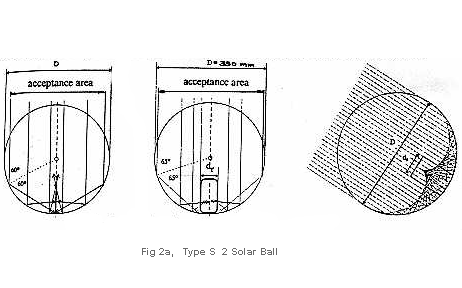
Medved et al., propose an interesting design ( 1996 ) called as 'SOLAR BALL'. Designated here as Type S 2 . It is an inflatable plastic ball with lower part of reflective material. Cooking vessel is kept at the base. It is an interesting variation but there appears to be some serious limitations with reference to size of the Ball as well as size and handling of the cooking vessel.
Recently the sperical geometry seems to have made a come back and we see that in India it-self. Such a mirror is being built in one of the centers.

Fig.2a1. Sperical mirror under construction. ( Source SCI site )
Parabolic geometry is well known, and it was probably the very first type of solar cooker. In this category, there are maximum variations. The reason for its popularity was the focus which was much better and sharper than that of other types of reflectors, but at the same time it was very sensitive to even a slight change in the position of the sun and hence the use of such reflectors meant constant tracking. Two types of parabolic reflectors are recognized in this review: (I) rigid parabolas, and (ii) collapsible or foldable parabolas.
Under this category, three major types have been identified: (I) Shallow parabolas, where the focus is outside the rim of the reflector, (ii) Asymmetrical parabolas, which are partial parabolas, and (iii) Deep parabolas, where the focus is within the rim of the reflector (Chart I).
There are just two variations in this design. PRS 1 is probably the oldest design, it has a firm U-shaped stand which holds the cooking post as well as the reflector. It is on record that Mouchet built such a cooker for the French troops of Napoleon III. The popular model, however, is known as the Wisconsin design of 1959 (Type PRS 1a, Figure 3). In this design, the reflector has a plastic base on which mylar was stuck. The design was not stable in the wind and there was also some problem of spilling of cooking material while the reflector was adjusted, and, hence, several designers have tried to improve upon it. Types PRS 1b to 1f are basically similar but for some modifications in the stand, orientation mechanism or materials used for the reflector, etc. The WHO design, PRS If, was most the sophisticated in terms of design and materials used. The Chinese type has a reflector, which has a slightly different rectangular shape and is made by sticking small pieces of mirrors on to a parabolic base. The vessel is kept on a separate stand to avoid spilling. Test data was not available. A Wisconsin design with 1.0 m reflector could boil 1 litre of water in 10-20 minutes, provided the assembly was aimed at the sun every 15 minutes. Recently, Kumar (1994) has conducted technical analysis of the parabolic mirrors. A lot of difficulty was encountered in the fabrication of parabolic reflectors, even with thin sheets of steel, so, many have presented easier methods. Srinivasan (1979) proposes a method wherein a circular sheet was cut out into suitably shaped petals, dimensions of which are carefully arrived at after detailed calculations. The petals are then joined to form the parabola, But this method too was found rather difficult, especially cutting out ‘curved petals’ from the sheet. So, a simpler method has been proposed – (Concept I) – which involves cutting the circular (1-1½ m) GI sheet into ‘petals’ with straight cuts up to the border of a 15 cm inner circle. Before cutting, 5 mm holes are drilled at the junction of this inner circle and the line of straight cuts. This would assist in easier overlapping (Figure 4). Then, the ‘petals’ are fixed overlapping one another, only at the edge. The width of this overlap was calculated using standard formulae (Baumeister et al. 1978; Kundapur 1995). However, the best parabolas could be fabricated only with the help of large lathes. VITA (1961) recommends several simpler techniques such as: (i) soil-cement depressions in the ground, (ii) moulded vermiculates, (iii) wire reinforced concrete shells, and (iv) paper-mache shells. The Boeing Company made hi-tech parabolas. Composite honeycomb structure was reinforced with fiberglass epoxy sandwich, to which a reflector material, polished aluminum sheet, was stuck. The reflector surface was further protected by vacuum deposited silicon oxide coating. It was reported that such a hi-tech reflector delivered about 437 W of power compared to 300 W of spun aluminum reflector of the same size. The size of the reflector is directly proportional to the performance of the cooker, and hence, it is a very important parameter. However, in most of the cases the size of the reflector was 1 sq. m only.

Source:- TIDE., March 1998, 8-1, pp 1-37, For Comments, suggestions,contributions contact < ashok_kundapur@yahoo.com>
The Chinese type PRS 1g had an area of about 1 ½ sq. m and the design proposed by Kulkarni (1978). PRS 1h, had an area of about 2 sq. m, this design also incorporates a cradle, enclosed suitably with a windshield, to hold the cooking vessel (Figure 5). Kulkarni reports that even chapatis could be fried in this cooker. This design was being marketed by M/s Jyothi Industries of Baroda. Another design with a 2 sq. m reflector was that of Walton et al. (1977). It is also known as Volta type (PRS 1e).
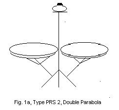
Prof. Ghai’s (Anon. 1970) parabolic concentrator was of a different type (PRS2, Figure 6). Evolved in the 1950s, the reflector was made from spun aluminium sheet. It had a hole at the centre through which projected an arm of the stand to hold the cooking vessel. Part of the reflector was cut out to enable easy access to the vessel. The entire unit had to be turned to face the sun.
These types of cookers did not become very popular, but The German News, 38 (June-July): 5-6, 1997, informs that 180 sq. m, parabolic concentrators have been installed at an institute at Mount Abu, to generate 600 kg. of steam at 16 bar pressure and cook food for 1200 people (Herms 1977).
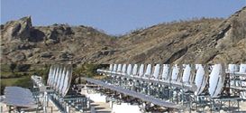
Fig 3a. Parabolic Mirror array form Mt. Abu ( Source SCI site )
Interestingly way back in 1980, I had proposed that a reflector/focussing device kept outside or in a suitable position would point focuss the image in the house which could then be used for cooking. This design you would see under Type ---but such a concept has already taken shape, independently at Bahai institute in India and with the help of a parabolic reflector kept out side the hut cooking even Chapathis are being cooked.
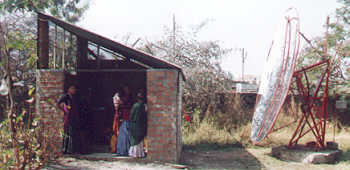
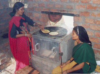
Fig 3a1 & 2 Photos from Bahai Institute ( Ref. their site on the web )
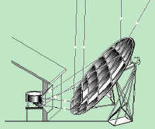
The following diagram shows the principle of Scheffler reflective cooker design in detail.
Prof. Von Oppen (1977), while working in India, proposed a do-it-yourself deep parabola (PRD 1). The focus of the reflector was inside the rim of the mirror, almost at the base. This design was unique in several respects; it made use of locally available materials like bamboo, paper pulp, aluminium foil for the reflector, and a unique and simple method for tracking the sun. The method was simple, a master mould was made to form the shape of the deep parabola, paper mache was smeared and dried, fine paper pulp was used to make the interior smooth, and this shell was reinforced with bamboo from outside. The interior of the shell was then coated with aluminium foil. The cooking vessel was hung from a string (Figure 7). Focusing was essential only once in 30 minutes. Provision was made for automatic tracking.

A pipe of about 15cm diameter and 1 m height was buried near the basket and filled with water. A bottle, half filled with water, was hung on into this pipe with the help of a string, and the other end of the string was tied to the basket. A small hole at the bottom of this pipe let out water and as the water level went down, the half-filled bottle sank, turning the basket suitably. However, effective cooking power was estimated to be only 250W. Initially, the cooker created a sensation. There were many difficulties in using the cooker, bright reflected light hit the eyes, it was difficult to handle the hot cooking vessel, and the basket was not stable in strong wind (GATE 1979).
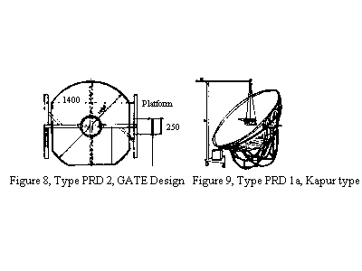
In 1979, the German Appropriate Technology Group (GATE ) proposed another less deeper parabola (PRD2, Figure 8). The reflector was 1.4 sq. m and was supported on a firm stand. The cooking vessel was to be hung from a separate stand (GATE 1979). Kapur (1982) described a similar design with further improvements in the stand like adding castor wheels (Figure 9).
Source:- TIDE., March 1998, 8-1, pp 1-37, For Comments, suggestions,contributions contact < ashok_kundapur@yahoo.com>
An asymmetrical parabolic reflector enables a cook to be as close as possible to the cooking vessel. In fact, in some of the earlier designs, like in case of Ghai’s design (Type PRS 2 and also in PRD 2), part of the reflector was cut out to facilitate this. But Tabor (1966) proposed a unique design (PRA 1). He used several smaller parabolic mirrors and arranged them in an asymmetrical parabolic configuration (Figure 10). The unit has a ‘U’ frame rotating on a pivot fixed to a strong base.
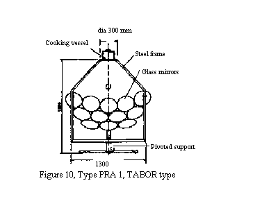
The frame has a stand at the top for the cooking vessel. Focal length of the reflector was 83 cm and the area was 0.8 sq. m. A temperature of 300o C could be attained though the effective cooking power was estimated to be 185 W.
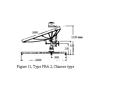
A Chinese design first described by Fang, Susan (1979) was indeed classic (Type PRA 2, Figure 11). The concentrator could be easily adjusted, as there was easy access to the cooking pot, which rests on a firm stand. The reflector had an aperture of almost 2 sq. m. Designers claim that it delivered 560 W of power, rather a high figure when compared to any other type of cooker. A prototype built here at Udupi performed satisfactorily.
Source:- TIDE., March 1998, 8-1, pp 1-37, For Comments, suggestions,contributions contact < ashok_kundapur@yahoo.com>
Concept II, PRA 2a envisages the use of strips of reflector. This would make the fabrication easy and may perhaps increase the efficiency and maintenance of the reflector. Further, an insulating cover around the cooking vessel would increase the efficiency and would add aesthetic value.
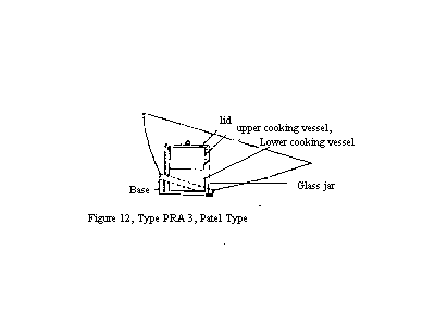
Patel (1982) , working independently, had evolved another design which he calls Suryakund (Indian Patent 233/234, Bombay – 80, and No 100/Bombay/81). This design has a deep asymmetric parabola without a point focus (Figure 12). The cooking vessel located inside a glass chamber at the focal point is easy to handle. But the focus would be a ring focus rather than a point focus. Designed with mass production in mind the reflector was moulded with ABS plastic to which aluminized polyester was stuck. The whole assembly can be easily rotated even with the cooking vessel to track the sun and all this makes this a novel design. However, the size of aperture is rather small and can be of use to campers or to people who wish to warm their food.
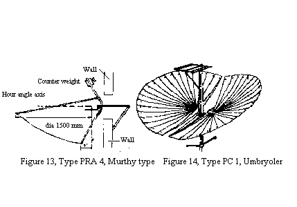
For those who wish to cook from inside the house,(or at least near the place where such shapes are used to trap radio waves,) Murthy (1982) presented an interesting variation designated here as PRA 4 (Figure 13). The device is a large asymmetrical parabola of aluminium sheet hooked on to a strong stand which can rest on a window frame (a provision had been made to adjust for the declination angle of the sun window.). The author calls it an offset feed parabola, a by-product of space technology (Figure 13). The author claims that the design delivered 994 W, which appears rather high ( the reflector used was only an aluminium sheet). Murthy suggests a south – facing window for better results. An insulated cover around the cooking vessel would increase efficiency. The design should incorporate easy folding facility such that it could be shifted easily from one window to another.
Source:- TIDE., March 1998, 8-1, pp 1-37, For Comments, suggestions,contributions contact < ashok_kundapur@yahoo.com>
| PREVIOUS PART TABLE 1a & 1b | NEXT PARTParabolic Concentrators | ||
For easy NAVIGATION use this chart.
OTHER LINKS are found under References S to W
click here for comments received
For Comments, suggestions,contributions contact < ashok_kundapur@yahoo.com>