

This page describes how the scanning camera was built, for background information and theory follow this link.The first and most important piece of equipment that had to be bought was the scanner. The final scanner choice was a UMAX PageOffice IIC, a sheet fed scanner that has an optical resolution of 300 dpi. Advantages of this particular scanner are that it is already driven by a motor making it easier to adapt to a scanning camera. It connects to a PC through a parallel port which means it could be used in conjunction with a laptop. Finally it was the last in stock at the store, therefore extremely cheap.
The scanner was pulled apart and the scanner hardware removed, including the CCD (charged coupled device) sensor, circuit board, cables, and the motor.
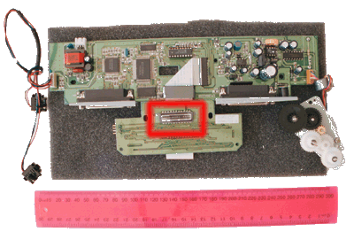
1. Hardware from the scanner, the CCD sensor is highlighted
A gearbox from a hobbyshop was adapted for the required gear ratio.
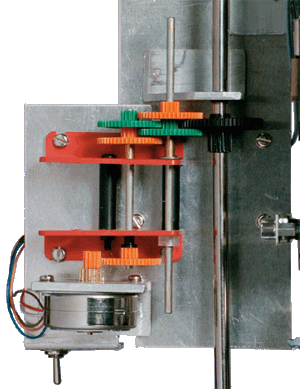
2. Scanner motor and Gears
The lens panel that goes in front of the CCD sensor was constructed from a thin piece of craftwood with a hole cut in the centre with the same dimensions as the CCD sensor. In front of the hole two small lenses from identical 110 format cameras were attached, with a thin piece of sheetmetal placed between them stretching back to the CCD sensor so that there is no light spill from the top lens onto the bottom half of the sensor, and vice versa. The periscope mirrors were glued on 45 degree angled supports which were then attached to the lens panel.
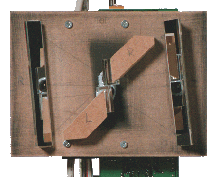
3. Lens panel supporting two small lenses and front surfaced mirrors to create
left and right displacement
The circuit board and motor mechanism were attached to a thin sheet of aluminium which in turn connected to a steel rod with a bearing so it could spin on the shaft without much friction. For the motor to rotate the whole camera around a final cog of 64 teeth was affixed to the centre rod. It is driven by the small 12 tooth green cog (as shown in image 2) .
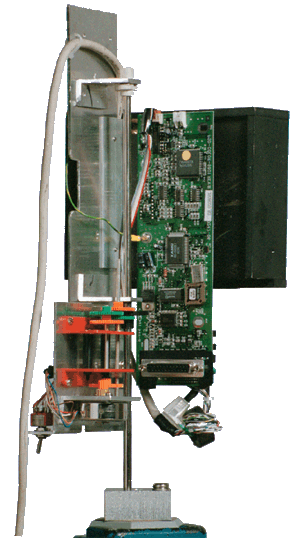
4. Motor and Circuit Board mounted on steel rod
The lens panel was then mounted in front of the CCD sensor with some foam wedged between, and screwed into place. By tightening or loosening the screws in small increments, the focus of the camera can be finely tuned.
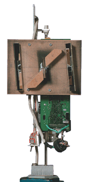
5. Lens Panel mounted on the front by four adjustable screws
Another part added to the scanner was a switch which reverses the direction of rotation of the motor. By using alternate clockwise and anti clockwise scanning, this avoids cable tangle. The resulting image flip is corrected in post processing.

Switch