
PROJECTS
 Josephson Junction Simulation
 Introduction
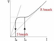 As said
elsewhere
a Josephson junctions is formed "weekly" connecting two superconductive
electrodes. The current-voltage curve of a typical real Josephson junction
is illustrated in the figure on the left. We can distinguish two separate
branches: the S (Superconductive or Stationary) branch and the R (Resistive)
branch. It turns out that this behavior is "quite" equivalent to the parallel
of a capacitor, a not linear resistance and a quantum phase driven current
source. This model goes under the acronym RCSJN (Resistively Capacitively
Shunted Junction Not linear), an extension of the original Stewart-McCumber
model in which was considered only a vanilla (i.e. linear) resistance.
Given that the quantum phase driven current is governed by Josephson
phase-voltage relations which are already not linear, Kirchoff rules for
the parallel produce a second degree not linear equation in the quantum
phase. A numerical integration method is used to resolve the system and
to evaluate phase-space trajectory. From the trajectory you can estrapolate
various information including the current-voltage curve and the asyntotic
behavior (i.e. the attractor).
 Numerical integration methods
used
A numerical integration method is the core of every program belonging to
this project. Some program can use an user selected method while some stick
with an hardcoded one. Following is a list of the methods currently implemented:
-
predictor-corrector Adams III and IV order method
-
predictor-corrector Adams-Moulton V and VI order method
-
one-step Runge-Kutta IV order method
Adaptive Runge-Kutta and Bulirsch-Stoer methods were evaluated but not
used.
The table below shows the ITest benchmark results for the implemented
methods on my machine.
Time in seconds to integrate RCSJN model over 10 millions steps
| Adams III |
20 |
| Adams IV |
21 |
| Adams-Moulton V |
37 |
| Adams-Moulton VI |
38 |
| Runge-Kutta IV |
77 |
 The programs
ANSI C applications
-
JJunction_IV
Generates the current-voltage characteristic curve of a (rf-driven
or not ) Josephson junction, averaging the voltage trajectory.
-
JJunction_TR
Generates the quantum phase, quantum phase time derivative (i.e. voltage)
trajectories for a (rf-driven or not) Josephson junction.
-
Lyapunov
Evaluates the Lyapunov exponents for the phase-space trajectory of
a rf driven Josephson junction.
-
Shapiro_Attractor
Calculates the (strange or not) attractor for the phase-space trajectory
of a rf-driven Josephson junction.
-
Shapiro_IV
Old version of JJunction_IV. Only evaluates rf-driven junctions.
-
Shapiro_scatterIV
Like Shapiro_IV but not using voltage averaging but voltage sampling.
Useful to discover period bifurcations.
-
ITest
Tests you system speed regarding RCSJN numerical integration.
 Downloadable
Win32 applications (compiled for Pentium+ machines) and ANSI C sources
are here.
Please note that no manual/document/explanation is included (sorry
but I do not have enough time for that); however you can request info at
my address.
silly Java 1.1 application
-
Josephson Junction Simulation (JJS)
Plots the quantum phase or voltage trajectory for a (rf-driven or not)
Josephson junction.
 Downloadable
Java 1.1 sources and classes (compiled with Sun's JDK 1.1.4) are here.
Please note that no manual/document/explanation is included (sorry
but I do not have enough time for that); however you can request info at
my address.
in the works
-
Microsoft MFC 4.x version
-
Borland JBuilder Java 1.1 version
 Shepp-Logan 3D Phantom synthetizer
 Introduction
The Shepp-Logan 3D Phantom (SL3DP) is a standard 3D phantom used to simulate
medical image reconstruction algorithms. The SL3DP is defined by the superimposition
of 12 ellipsoids each having a slightly different density. While the SL3DP
was mainly thought for human head simulations, it is believed to represent
rather well the generic radiological problem to discriminate small density
discontinuities which can suggest a tissue lesion. Each ellipsoid belonging
to the phantom is defined as in the figure on the left. Below you can find
the table listing each ellipsoid definition.
Shepp-Logan 3D definition by superimposition of 12 ellipsoids
| Center coord x |
Center coord y |
Center coord z |
1st semiaxis a |
2nd semiaxis b |
3rd semiaxis c |
Equatorial angle |
Polar angle |
Density |
| 0.0 |
0.0 |
0.0 |
0.69 |
0.9 |
0.92 |
0 |
0 |
2.0 |
| 0.0 |
0.0 |
-0.0184 |
0.6624 |
0.88 |
0.874 |
0 |
0 |
-0.98 |
| -0.22 |
0.25 |
0.0 |
0.41 |
0.21 |
0.16 |
0 |
72° |
-0.02 |
| 0.22 |
0.25 |
0.0 |
0.31 |
0.22 |
0.11 |
0 |
-72° |
0.01 |
| 0.0 |
0.25 |
0.35 |
0.21 |
0.35 |
0.25 |
0 |
0 |
0.01 |
| 0.0 |
0.25 |
0.1 |
0.046 |
0.046 |
0.046 |
0 |
0 |
0.01 |
| -0.08 |
0.25 |
-0.605 |
0.046 |
0.02 |
0.023 |
0 |
0 |
0.01 |
| 0.06 |
0.25 |
-0.605 |
0.046 |
0.02 |
0.023 |
0 |
90° |
0.01 |
| 0.06 |
-0.625 |
-0.105 |
0.056 |
0.1 |
0.04 |
0 |
90° |
0.02 |
| 0.0 |
-0.625 |
0.1 |
0.056 |
0.1 |
0.056 |
0 |
0 |
-0.02 |
| 0.0 |
0.25 |
-0.1 |
0.046 |
0.046 |
0.046 |
0 |
0 |
0.01 |
| 0.0 |
0.25 |
-0.605 |
0.023 |
0.023 |
0.023 |
0 |
0 |
0.01 |
 The program
The synthetizer program syntax is:
slps xcube ycube zcube [X][Y][Z]
where xcube, ycube, zcube are the dimensions (in pixels) along x, y and
z axis. A binary data file (sl_pha.dat) is saved containing full floating
values per voxel. The optional X, Y and Z switches tell the program to
save also section images using portable grey map (PGM) binary format.
Currently the synthesis is done on the cube of real dimensions 2x2x2.
 Request
ANSI
C++ sources and/or Win32 apps
 Shepp-Logan 3D Phantom projector
 Introduction
In order to simulate cone beam 3D CT you need to simulate 2D projections.
In this case the projector provide to project the Shepp-Logan 3D Phantom
(SL3DP). Given SL3DP projections you can test your backprojector by comparing
recostruction values (i.e. density spatial distribution) with "true" values
obtained using slps.
 The program
The projector program syntax is:
where detsw and detsh are the plane detector semiwidth and semiheight and
where numpro are the number of projections (that is the projection angle
moves from 0 to 2PI in 2PI/numpro quanta). Please note that currently the
plane detector and X source position are hardcoded and that the detector
is not curved (i.e. semicylindrical surface) but strictly plane.
 Request
ANSI
C++ sources and/or Win32 apps
 Cone beam 3D filtered backprojector
 Introduction
The cone beam 3D filtered backprojector should reconstruct a solid 3D object
by opportune elaboration of its 2D cone projections. An approximate reconstruction
algorithm was provided by Feldkamp, Davis and Kress (hence the name of
FDK algorithm) in the eighties. The algorithm is quite simple but somewhat
computationally intensive.
 The program
The cone beam program syntax is:
Currently the reconstruction is done on a 128x128x128 3D cube (hardcoded)
using bilinear interpolation. Results are quite good (see below).
 Request
ANSI
C++ sources and/or Win32 apps
 About performance
The FDK algorithm is tricky to optimize any further. The version currently
available is written using floating-point-math. Below you can see the performance
results on my machine for the reconstruction
on the given volume for 40 256x256 projections (bilinear interpolation).
FDK Cone Beam reconstruction performance
|
Reconstruction step
|
64x64x64 cube (2 MB)
|
128x128x128 cube (16 MB)
|
256x128x256 (64 MB)
|
| FFT + Filtering + FFT -1 |
11 sec |
11 sec |
11 sec |
| FDK Backprojection |
13 sec (half a min total) |
110 sec (2 min total) |
570 sec (9 min total) |
Note the memory occupation for the given array of doubles. Consider
that even at 256x128x256 MB Win NT is bogged down by virtual memory. That
was the reason why I did not test on a 256x256x256 cube. The memory occupation
would reduce by a factor 2 using floats instead of doubles. Btw you really
need 128 MB (physical) and fast virtual memory (i.e. HDs) to take the reconstruction
on more detailed volumes.
I've thought many times about ways of making the algorithm any faster.
The thing I've noted is that the most time-consuming operation is pixel
interpolation. In particular float-to-integer conversions seems to be the
main reason of slowness. These conversions are mandatory even in order
0 (nearest neighbour) interpolation: bilinear interpolation introduces
another bog-down factor but that is not crucial in my opinion.
These facts can suggest to ditch floating-point-math and use fixed-point-math:
in fixed-point-math (fpm) the conversion to integer is pretty istantaneous
(just a bit shift). fpm was the main way of representing real numbers in
the good old days of computing when fpu processors were very expensive.
In those days cpus did not include floating-point units (do you remember
68030/68882 ?) and so programmers had to program using fpm. Nowadays every
cpu includes a fpu so many programmers recommend not to use fpm just because
it's not any more convenient. Hey even Quake does not include fpm anymore!
Consider moreover that using the fpu is a kind of free-lunch cause the
fpu can work in parallel with the cpu integer unit: the amount of parallelism
is clearly application dependant, for the cone beam reconstruction however
I expect the parallelism to be quite low.
fpm has its flaws (lack of general precision) but these are not important
in a not so demanding application as a cone beam reconstruction program.
The main problem with fpm nowadays is lack of support: no standard math
library, you have to code basic (and not so basic) operations in assembler.
I think this kind of work is not feasible for me right now. If anything
changes about this project (more interest) I may reconsider though.
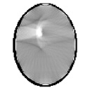
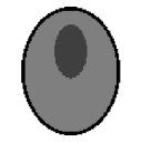
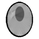
 Sample images
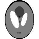
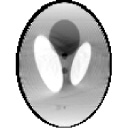
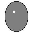
Below you can find the comparison between the most interesting sections
of the "exact" Shepp-Logan phantom and the reconstructed ones (via cbct).
Every section was calculated on a 128x128x128 voxels 3D cube starting from
64 projections on a detector plane of 128x128 pixels. As you can see results
are quite good even using few projections and low resolution geometry.
| Exact section |
Reconstructed section |
|
 |
 |
Plane xz.
79 y section (y = + 0.234). |
 |
 |
Plane xy.
40 z section (z = - 0.375). |
 |
 |
Plane xy.
90 z section (z = + 0.406). |
 1D Fourier Farm wrapper
 Introduction
Around the Internet you can find many Fast Fourier (1D) implementations.
During a research job of mine I have tested the majority of public domain
FFT libraries for Windows 9x/NT/2000. My conclusions were:
-
If you need to transform 2^n points, use Intel Math Kernel Library. Look
at http://developer.intel.com/vtune/perflibst/mkl/index.htm.
-
If you need more general transformations, use the Fast Fourier in The West.
Look at http://theory.lcs.mit.edu/~fftw/.
Intel MKL (version 3.1 at the time of writing) is provided as Windows DLLs
and is rather huge (> 1 MB).
FFTW (version 2.1 at the time of writing) is provided as GNU C source
code.
 The wrapper
My FourierFarm wrapper is a 1D Fourier Transform Win32 DLL. The only exported
function provided by FourierFarm.dll is
< FourierFarm* GetFourierFarm_Best(int npToPad,bool
isPad) >
where npToPad is the number of points requested for transformation,
isPad a flag for zero padding and FourierFarm* a pointer to a C++ class
with which apply FFTs to 1D arrays.
The actual FFT code used depends on the presence of FFT libraries. If
Intel MKL library is found and the number of points is of kind 2^n, then
MKL code is used. If the number of points is not a power of 2, the wrapper
looks for FFT libraries in this order: FFTW, MKL. If nor MKL nor FFTW libraries
are found, the wrapper uses the built-in FFT code based on Duhamel split-radix
algorithm written by me in the past.
 Requirements
The wrapper is useful for C++ developers only.
If you intend to use Intel MKL code, look at the Intel Developer site
http://developer.intel.com/vtune/perflibst/mkl/index.htm
and install MKL libraries (*.dll) in the system/system32 directory.
If you intend to use FFTW code, download from http://theory.lcs.mit.edu/~fftw/
the FFTW source code. Then you will need to build a fftw.dll library from
fftw/rfftw sources. Move the fftw.dll so created in the system/system32
directory.
 Download
Win32
FourierFarm.dll and C++ header
 Request
Win32
C++ sources
Stefano Agostinelli - agostinellis@bigfoot.com
This page hosted by  Get your own Free Home Page


 As said
elsewhere
a Josephson junctions is formed "weekly" connecting two superconductive
electrodes. The current-voltage curve of a typical real Josephson junction
is illustrated in the figure on the left. We can distinguish two separate
branches: the S (Superconductive or Stationary) branch and the R (Resistive)
branch. It turns out that this behavior is "quite" equivalent to the parallel
of a capacitor, a not linear resistance and a quantum phase driven current
source. This model goes under the acronym RCSJN (Resistively Capacitively
Shunted Junction Not linear), an extension of the original Stewart-McCumber
model in which was considered only a vanilla (i.e. linear) resistance.
![]() Request
ANSI
C++ sources and/or Win32 apps
Request
ANSI
C++ sources and/or Win32 apps
![]() Request
ANSI
C++ sources and/or Win32 apps
Request
ANSI
C++ sources and/or Win32 apps
![]() Request
ANSI
C++ sources and/or Win32 apps
Request
ANSI
C++ sources and/or Win32 apps


![]() Requirements
Requirements
![]() Download
Win32
FourierFarm.dll and C++ header
Download
Win32
FourierFarm.dll and C++ header
![]() Request
Win32
C++ sources
Request
Win32
C++ sources
![]() Get your own Free Home Page
Get your own Free Home Page