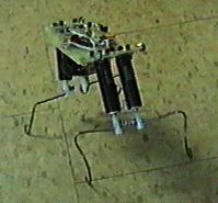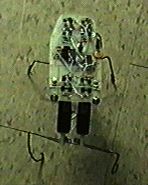


top view of my 4 motor walker
Description
This is my first 4 motor walker. It's also responsible for many of my "firsts." It's my first walker with a board based frame. The circuit board actualy becomes the frame for the motors and the legs! I also completed the whole bot in a single piece board (there is a cut and reconection at an angle to create the angled front, but it's simply an angled section). It's very sturdy, and I designed it in under 2 hours! The motors shown on the images will be replaced with stronger motors. These are too weak to lift the robot sufficiently. I'm using these motors for a snake robot (14 segments using 13 motors!!!). This robot is a very high quality design, and it'll be kinda sad to remove and replace the motors, cause the bot was named for the motors source (MECI). I'll still keep the name, however I have to replace the motors though. I'll probably use standard hobby servos, which aren't that bad. It'll actualy reduce the height, making it even more stable! I hope this robot turns out well! It should look as cool as it does now. It'll have some extra wires maybe. This robot opperates on the same principal as Walkman Jr. (my first 2 motor walker (and first robot for that matter))! It walks by "falling" forward. It uses a 4 Nv microcore (Nv stands for Nervous network). The microcore is a loop of Nv units that cycle pulses through to opperate the device. Mark Tilden designed the microcore using a 74HC14 schmitt triggered inverter, a resistor, and a capacitor.
Mechanics
This 4 motor walker is unique in that it's mechanical design is almost Identical to a 2 motor walker. The robot moves by "falling" forward. It lifts it's front legs, pushes with it's back. It's center of gravity needs to be as close to the point where two imaginary lines would cross if each line attached to the feet of the legs diagonaly apart. To tell if it has a proper center of gravity, tilt the front legs and see if it can tip from front to back. If it stays where you tip it, it's pretty good. The front legs should be tipped up at approximately 30 degrees. The legs shapes you need to play with. Try different things. You can use servos to opperate the legs. The servo's built in potentiometer can be used to bias a microcore or if you use a microcontroler, the servo does not need modification.
This walker can't realy turn efficiently. you can bias the rear legs to make it turn a wide radius, but it's realy not too feasible for a beginner, and it's actualy easier with a 2 motor walker!
Electronics
The Nervous Network: MECI IV M uses a nervous network. Nervous networks are very similar to Neural networks, however there are important diferences. Nervous networks, in the most basic sense, imitate neurons that are responsible for reflexes. Each neuron is a single inverter. The inverter MUST have a schmitt trigger. A schmitt trigger allows a signal to fluctuate a little bit without rapid triggering of the output. There are two thresholds, a high and a low. if the input is low and rises, the output won't go low until the input hit's the high threshold. if the input goes back below the high threshold, the output won't change, but if it goes far low to the low threshold, then the output will go back to high. This allows leeway for the input. It's a very interesting system
The 74HC14 hex schmitt inverter is the most popular inverter for use in nervous networks. They can be chained, or looped. A loop of nervous networks are called a microcore. the inverters are joined by a capacitor, usualy between .1µf and .3µf (I like using .22µf capacitors). A resistor is attached to the inputs. 1 Mega Ohm (M*) is a good value to use with .22µf capacitors. It's easier to alter the value of the resistors than the caps. You can also use the servo pots to bias the microcore. attach the two oustide pins to the inputs of the neurons that drive that servo. Attach the center lead through a resistor to adjust the value properly, and then it to ground. if you attach the microcore straight with fixed resistors, than a fixed resistor on the inputs and to ground. The outputs of the microcore can go to LEDs, drivers, or other devices.
The Nervous network and Microcore are patented my Mark Tilden. It's a realy interesting device. It has many uses!
The Motor drivers: I used an H-Bridge to drive the motors on this particular robot. The H-Bridge is a rather ingenious design. I don't know who invented it, but it's an EXCELENT design. It uses 4 transistors to route electricity through a motor. There are two inputs. One attaches to one pair of transistors and the other to the other pair. The schematic resembles an "H" (hence the name). When both are on or both off, the transistor with the polarity matching the input activates. In this case, it's equivalent to connecting both wires of the motor to (+) or (-) on the battery. It won't work. If one OR the other , but NOT both, are on, then one side of the motor is routed to (+) or to (-) and the other side remains at it's former polarity. This creates a (+) on one side and a (-) on the other, or vise versa, depending on which line is active. This makes the motor turn one way or the other. By attaching the microcore or a microcontroler to the inputs, you can control a motor. This requires a DC motor, which can be a hacked servo. remove the electronics, but leave the pot and motor (some servos use the pot as the axle for the main gear (one I had did anyway). Attach the driver outputs straight to the motor and the pot can be attached to the microcore (optionaly).
Walking
The microcore is attached to the H-Bridge drivers. There are four neurons, and 4 motors (a neuron for each direction the front pair and rear pair of motors can turn. NOTE: the front motors are electronicaly linked as are the rear motors are linked to each other). It's IDENTICAL in operation to Walkman Jr, just with 4 motors instead of 2. The sequence I use is as follows:
Front Clockwise, Rear Counter Clockwise, Front Counter Clockwise, and Rear Clockwise
The front legs lift, the rear legs push forward, the front legs shift balance and fall forward and the rear legs push again. It continues this in a loop and creates forward motion. To reverse, you can reverse the rear motor, however this robot does not have that feature.
This robot is very simple. The board is nearly all the work. This frame can be made to hold servo motors, and can be mounted using thick guitar or piano wire to support the circuit board. I'd recomend using strips of PCB copper clad or solid solderable metal strips (like brass or thick wire). Aluminum or any unsolderable material can be used, as well as plastic, but remember, the board mounts best using piano or steel guitar wire.
If you have questions, regarding construction, contact me via the rconnect e-mail address in the navigation bar above (or below if you scroll down)
There is also plans for a diferent style 4 motor walker on the main robotics page. This one will be far more agile! It's based on my 3 motor design. The 4 motor design can be further enhanced with a 5th motor to allow it to turn. You can also cut the lift motor from the rear and replace it with a waist motor for turning to produce a 4 motor walker with easy turning and good lift (the 5 motor walker has the best lift, propulsion, and has a turning motor on the waist. MECI IV M was actualy a design mistake. I was originaly doing a 2 motor walker, but I realized the MECI motors couldn't lift a walker, so I added 2 more, one for each leg, but my mistake was that now it had almost 2x the weight and one motor is still all that lifts. I then planned on mechanicaly linking the motors, and then decided to scrap the MECI motors for servos. The MECI motors can be used for my 14 segment snake I'm planning (if none of the motors get damaged during that time. I've already accidentaly ruined 3 and was only able to fix one). Basicly, MECI IV M is a 2 motor walker, but it uses a motor on each leg, making it more natural looking, and more power hungry! MECI IV M would have been completely scrapped if it weren't for how cool it looks with it's two metal cased photoresistor eyes and single board aproach. I just can't throw away a robot I've spent nearly 24 total hours on, even if I can save $40 on servos. It also goes to prove one of the quirks of BEAM evolution! A robot doesn't need to work well as long as it looks so cool that everytone loves it! It's actualy very similar to the "cuteness" factor that causes humans to adore babies, even though they can't do a single thing on their own but cry and "mess" themselves! (:
| E-Mail me at: richfile@rconnect.com | The Richfiles TI Graphing Calculator Page |
| The Richfiles Model Building Page | The "Mopar Brothers" Muscle Car Page |