Distributed arithmetic design
Introduction
Distributed arithmetic is an important algorithm for DSP applications. It is based on a bit level rearrangement of the MAC "multiply accumulate" operation to replace it with set of addition and shifting operations.
Theoretical derivation
Download the ps file or the pdf file
for the theoretical derivation
Practical Derivation
This algorithm is based on the scaling accumulation algorithm described in [1]. This accumulator takes one parallel and one serial inputs. The parallel input in DA algorithm is considered to be a constant. Several Scaling accumulator units can be used in parallel to do the MAC operation for many terms. The next figer shows two serial inputs (A,B) that are multiplied by the constants (C1,C2). These constants and the AND operation with input bit can be considered as product terms.
 The output of this circuit is A*C1 + B*C2
If we moved the adder-shifter circuits at the end of the circuit and using single circuit we eleminate large number of adders = N number of inputs to only one. The constants with the AND operators and partial sums can represent product terms that can have predefined equations. These equations can be implemented using ROM where its contents are defined by the constants and its address the inputs bits (A,B in our example)
Since only one bit of each input goes to the ROM address The rom contents is defined as follows assuming we have three inputs:
Addr (000) => 0
Addr (001) => C0
Addr (010) => C1
Addr (011) => C0+C1
Addr (100) => C2
Addr (101) => C0+C2
Addr (110) => C1+C2
Addr (111) => C0+C1+C2
This algorithm can be implemented in many different approaches depending on he system constraints. For more information refer to the links below.
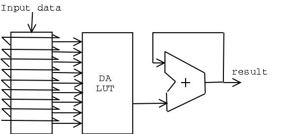
The Implementation I used is shown in the next figure where the first block is a 2D shifter that is connected to the address lines of the Distributed Arithmetic Look-up Table (DALUT). The result is added serially to produce filter's result.

Implementation
The VHDL code is available on the opencores CVS under arith_cores modules.
- The design can take N number of tabs and M number of bits for data and constants. These parameters can be changed in DApkg.vhd.
- The current design has 4 tabs and 8 bits data size.
- all numbers are unsigned
- The output become valid after M clocks and it is indicated by valid signal.
- Overflow signal indicates an overflow in the result if it exceeds M the bits.
- a pipeline is used between the da lut result and the serial adder to speed up the design.
- The input is sampled on the Mth clock.
- There is a software written in both C and perl to generate the system parameters
- Check the JBits implementation of the core which is suitable for run time reconfiguration
Source files:
- da.vhd : defines the serial addition and input buffers.
- dalut.vhd : defines the DA look up table.
- DApkg.vhd : defines some system constants, parameters and components
- Mempkg.vhd : defines some procedures
- da_tb.vhd: is the system test bench,
- dapkg_gen.c: is a C program that generates Dapkg.vhd in order to customize all system parameters
- da_pkg_fract.c: dapkg_gen modified to accept negative and fractional coefficients by James Edgar
- dapkg_gen.pl: is a perl program that generates Dapkg.vhd in order to customize all system parameters
Advantages
- It reduces the logic needed to implement MAC operator to only adders and shifters
- It can be implemented on LUT "Look-up-table" based FPGAs without wasting resources
- It has several implementation based on several trade-offs
- Most FIR filters have constant operators so using DA algorithm they can be implemented with very custom circuits.
Resources and references
 Last update: 30 September 2000


