[ Japanese | Back to Index ]

Jumper Settings for Vision Top S7-MVP3 Mother Board

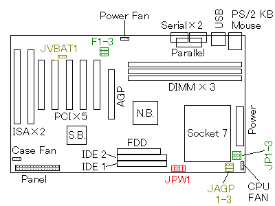
Mother Board Top View

Mother Board Top View

You see the jumper settings in this direction.
"N.B.", "S.B." are North Bridge, South Bridge of the chipset.

  1. CPU core voltage (JPW1, Red)
  2. Short pins in the vertical direction of the picture.
    Only the folowing voltage settings are listed on the manual.

    · A A A A
    · V V V V
    2.0V   A · · · ·
    V · · · ·
    2.1V   · · A · ·
    · · V · ·
    2.4V   · · · A ·
    · · · V ·
    2.8V   A · · A ·
    V · · V ·
    2.9V

    · · A A ·
    · · V V ·
    3.2V   A · A A ·
    V · V V ·
    3.3V   · A A A ·
    · V V V ·
    3.4V   A A A A ·
    V V V V ·
    3.5V

    The proper voltage for AMD K6-3/450MHz is 2.4V.
    2.2V is not listed on the manual. To use K6-2(slower than 450MHz), set 2.1V and run CPU saving energy.

  3. CPU FSB clock frequency (F1-F3, Green)
  4. Short pins in the horizontal direction of the picture.
    60MHz - 112MHz can be set, but 95MHz is not supported.

    F3
    F2
    F1
    < > ·
    < > ·
    · < >
    60MHz  < > ·
    < > ·
    < > ·
    66MHz  · < >
    · < >
    · < >
    68.5MHz  < > ·
    · < >
    < > ·
    75MHz


    1111
    F3
    F2
    F1
    < > ·
    · < >
    · < >
    83MHz  · < >
    < > ·
    · < >
    90MHz  · < >
    < > ·
    < > ·
    100MHz  · < >
    · < >
    < > ·
    112MHz
    1111

    Normal clock frequency for K6-3/450MHz or K6-2/300MHz is 100MHz.

  5. CPU clock multiplying rate (JP1-3, Green)
  6. Short pins in the horizontal direction of the picture.
    6X is available for K6-2 XT core.

    JP3
    JP2
    JP1
    < > ·
    < > ·
    < > ·
    1.5/3.5  < > ·
    · < >
    < > ·
    2.0/6.0  · < >
    · < >
    < > ·
    2.5  · < >
    < > ·
    < > ·
    3.0 


    1111
    JP3
    JP2
    JP1
    < > ·
    · < >
    · < >
    4.0  · < >
    · < >
    · < >
    4.5  · < >
    < > ·
    · < >
    5.0  < > ·
    < > ·
    · < >
    5.5 
    1111

  7. Clock frequency rate of PCI, AGP and CPU FSB (JAGP1-3, Yellow)
  8. Short pins in the horizontal direction of the picture.
    11
    JAGP3
    JAGP2
    JAGP1
    · < >
    · < >
    · < >
    60-75MHz
    PCI=1/2
    AGP=1
      < > ·
    < > ·
    · < >
    83-112MHz
    PCI=1/3
    AGP=2/3

  9. Reset BIOS settings (JVBAT1, Yellow)
  10. Short pins in the horizontal direction of the picture.
    1
    Normal< > ·
    Reset all· < >

  11. Connection to front panel
  12. Connect the cables from the case in the horizontal direction of the picture.

    Turbo LED, Power LED, Key Lock, Speaker, Sleep Switch

    @ @ · @ @ @ @ @ · @ @ @ @ · @ @
    @ @ @ · @ @ · @ @ @ @ @ @ @ @ @
    
    Turbo Switch, Reset Switch, IDE Access LED, IrDA Connector, Power Switch

    You need to connect at least, Power Switch, Power LED, Reset Switch, IDE Access LED, Speaker.
    LED has polarity. If you connect LED connector in the opposite direction, LED doesn't work.

BIOS Update

How to update BIOS :
  1. Prepare a floppy disk to boot Windows 98/95/MS-DOS.
    To get one, format a floppy disk by Windows Explorer or DOS command, with "Boot Disk" / "Transfer the System" option.
    The disk should not have "DEVICE=EMM386.EXE" description in "\CONFIG.SYS" file.
  2. Boot your PC by the floppy disk.
    Do not go into "Virtual 86 mode".
  3. Execute "awdflash.exe" giving the BIOS data file name "mvp3C824.bin".
    You can not execute it from "DOS Window" on Windows.
  4. Reboot your computer.

Vision Top Home Page / S7-MVP3

Japanese Back to Index Back to Index My Computer My Computer

1