Headclone Headphone Amplifier
Op-amp driver and Linkwitz crossfeed
Introduction : Circuit Schematic : Layout
Introduction
This Headclone takes the standard non-inverting op-amp circuit as found in Chu Moy's Pocket Headphone Amplifier, the Linkwitz Crossfeed Filter, also elaborated by Chu, and various insights from the Gainclone project - itself also a non-inverting op-amp circuit.
The Amplifier Circuit
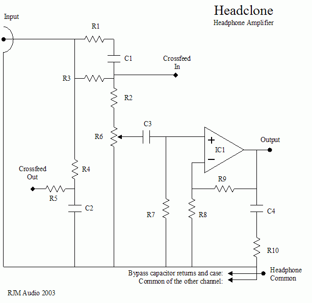
The circuit is shown below.

C1, C2 and R1-R6, make up the Linkwitz crossfeed filter. The volume control, R6, is in series with R2 and part of the filter. Normally the volume control would be at the input followed by the crossfeed filter with a op-amp buffer in between to keep the impedances low. The configuration shown here removes the need for the input buffer. A coupling capacitor C3 blocks the DC, and R7 is the input resistor for the amplifier. The gain is set by the ratio of the inverting resistor and the feedback resistor R8 and R9. The Zobel network on the output, C4 and R10, is optional but recommended.
Parts values:
| R1 | 3k3 | crossfeed |
| R2 | 1k | crossfeed (approx. 2k2 - R6) |
| R3 | 22k | crossfeed |
| R4 | 7k5 | crossfeed |
| R5 | 7k5 | crossfeed |
| R6 | 1k | stereo logarithmic |
| R7 | 22k | non-inverting input |
| R8 | 680R | inverting input (gain 30x) |
| R9 | 22k | feedback |
| R10 | 22R | Zobel (optional) |
| C1 | 10 nF | crossfeed |
| C2 | 47 nF | crossfeed |
| C3 | 4.7 µF | input (Black Gate N) |
| C4 | 10 nF | Zobel (optional) |
| IC1 | OPA2134 | OPA2604 etc. |
The crossfeed values are the equivalent of Chu's in terms of effect.
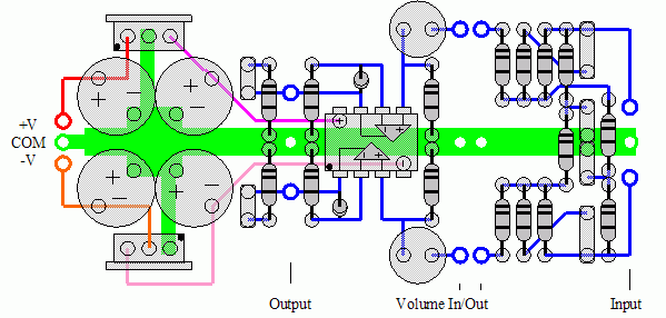
The op-amp used in the layout below is the dual version OPA2134, although the single OPA134 can of course be used with a different parts layout.
A 1k volume potentiometer is called for. The Clarostat 585 is the only 1k dual logarithmic potentiometer that I'm aware of. Alternatively a rotary switch could be made into a stepped attenuator.
Recommended Power Supply
The transformer is at least 50 VA and has two 7 V secondaries. One or two full-wave rectifiers, 100 V / 1 A or larger. Fuse.
Next, placed as close to the amplifier as possible or integrated as part of the same board, is the voltage regulation circuit. In the simplest variation, the fixed voltage 3-pin regulators, e.g. LM7805 and LM7905, are used with 480 µF to 1000 µF on the input and 100 µF to 220 µF on the output terminal.
Adjustable regulators can be used instead for improved performance.
Layout
Here is an example layout using a dual op-amp. The unregulated power supply is not shown.

rjm003.geo at yahoo.com

|