An Op-amp Phono Stage
Two-stage circuit with passive RIAA equalization.
This is an elaboration of a well-known and classic op-amp topology for phono preamplifiers. The limitations of the circuit are discussed, and hints given on how to best optimize it for maximum performance.
The Amplifier Circuit
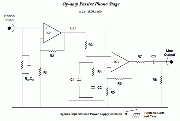
Originally sourced from the OP606 datasheet, where it is attributed to Walter G. Jung. The circuit can be used as-is without further modification, but I have tweaked it slightly for the version shown here.
| Component | Value | Description |
|---|---|---|
| Rin | 47k | Or as specified by the cartridge manufacturer. |
| R1 | 680R | |
| R2 | 22k | |
| R3 | 7.22k | RIAA (7.32k can be substituted) |
| R4 | 1.05k | RIAA |
| R5 | 680R | |
| R6 | 22k | |
| R7 | 47R | Defines the output impedance. Isolates the output stage from cable capacitance, improving stability. |
| R8 | 33k | Keeps the output at zero volts DC. Value not critical. |
| Cin | ** | Optional, set as recommended by cartridge manufacturer. |
| C1 | 104nF | RIAA (1x 0.1 µF) |
| C2 | 303nF | RIAA (3x 0.1 µF) |
| C3 | 4.7µF | Output coupling. Must be non-polar. 3.3 2.2µF, 2.2µF can be substituted. |
| U1 | OP27 | Input stage. Other op-amps can be substituted. |
| U2 | OP27 | Output stage. Other op-amps can be substituted. |
RIAA values shown in bold. The exact values listed above theoretically give a response accurate to ±0.01 dB. To even approach that the RIAA resistors and the gain determining resistors R1, R2, R5, and R6 should be 1% types or hand matched to within that tolerance. The capacitors must be hand picked to the same 1% tolerance with the help of an accurate meter. In practice deviation up to 3% is accpetable, especially if it is consistent between channels.
Circuit Description
The input voltage is generated across the load resistor Rin and amplified by the first gain stage IC1. The gain is ( 1 + R2 / R1 ), with the values listed its 30 dB. R3, R4, C1, and C2 form a frequency dependent voltage divider that does the RIAA equalization. Treble is attenuated by 40 dB, midrange by 20 dB, while the bass frequencies are left as-is. The output from the voltage divider is amplified by the second gain stage IC2. The gain is ( 1 + R6 / R5 ), with the values listed its 30 dB. The total midrange gain is 30 dB (stage1) - 20 dB (passive RIAA) + 30 dB (stage2) = 40 dB. Its called passive equalization because the frequency shaping is all done by attenuation using resistors and capacitors. The gain of both op-amps is constant over the audio bandwidth.
A passive filter is inefficient. In the midrange 90% of the signal is thrown away. In the treble 99% of the available signal is thrown away. A second gain stage is required, both to boost the signal amplitude and buffer the high output impedance of the filter. This has three negative disadvantages.
- Cost, space, and power requirements of the additional gain stage.
- Noise and distortion associated with attenuating the signal and then amplifying it again.
- Difficulty in grounding layout when using a common power supply with two non-inverting gain stages, in the case where the output of the first stage is the (non-inverting) input of the second.
An additional, often cited, problem with the circuit is the lack of voltage headroom in the first stage.
In comparison the VSPS doesn't suffer from any of these issues. Its simpler and cheaper, and recommended if you are looking for an op-amp phono stage for moving magnet cartridges.
Those dead-set on passive equalization - and don't want to use tubes, which at least don't suffer from the grounding and headroom issues - read on.
The circuit is optimized by fine-tuning the gain and the impedances, choosing the right op-amp to match, and finally getting the ground layout right.
There is relatively little room for tweaking the component values. I reduced the gain of the first stage slightly from the 34 dB to 30 dB and increased the second stage from 26 dB to 30 dB to compensate. This was done mainly to improve the headroom slightly. I increased the resistances R1, R2, R5 and R6 considerably. This will make the circuit easier to drive and argueably better balances the impedances on the non-inverting terminals, but may also increase the noise floor slightly depending on the op-amp used. The passive equalization circuit can be rebuilt with any multiple of the values listed, with proportionally higher or lower input and output impedances. Higher impedances generate more noise at the input of the second gain stage but are easier for the first stage to drive. I stuck with the original values, these seem a good balance. This input impedance of the RIAA network is 8 kohms and the output impedance about 800 ohms in the midband.
I chose the OP27 for both the input and output. This is a low noise, precision op-amp with bipolar inputs. Its cheap, readily available and I've used it with good results in the phonoclone. FET input, audio op-amps like the OPA134, OPA606, and OPA604 can also be substituted. This circuit can also be built using a dual op-amp. The OPA2134 and NE5532 are both appropriate.
Power Supply
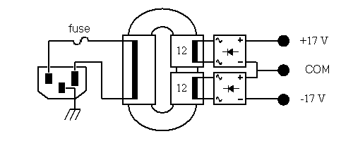
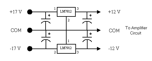
The power supply and regulation circuitry is considered separately. I recommend a large, shielded, low noise torroidal or R-core transformer with two 12 V output windings, with your choice of diode rectifiers.

No filter capacitors are required in the external power supply, as these are part of the regulation circuit placed right next to the amplifier circuit. In its simplest form, you need two fixed voltage regulators, LM7812 and LM7912 for example, with about 480 µF of capacitance connected on the input of each regulator and about 100 µF at the output. Higher performance regulation circuitry can of course be substituted.

Layout
Under development. This circuit does not lend itself to a "nice" layout.
Notes
rjm003.geo at yahoo.com

|
