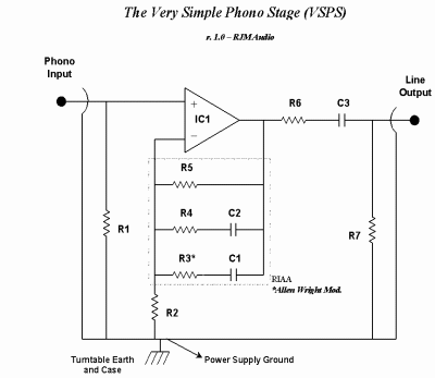
The VSPS
Very Simple Phono Stage
Presenting a simple, versatile phono stage using a bare minimum number of parts and the following features:
- 27 parts per stereo unit. Low parts count makes it cheap to build and easy to optimize.
- Wide choice of op amps. Just about any op amp can be used in this circuit.
- Accurate RIAA equalization obtained using common, standard value components. Uses Allen Wright's modified curve, with the additional zero at 3.2 µS.
- User variable gain. The circuit can be easily adapted to work with moving magnet and medium-to-high output moving coil cartriges.
- Low power consumption.
- Single stage, active equalization, non-inverting topology.
This circuit is appealing for beginners, of course, but the simplicity also offers more experienced builders the chance to evaluate and optimize each individual part. Taking my cue from 47 Labs I would also like to think there is an inherent benefit of a simple circuit, sonically, coming from the tighter layouts and better grounding arrangements - the direct result of having fewer parts to deal with. The VSPS is the most popular circuit I have developed, many people have successfully built it. Its proved to be an amazingly rugged and reliable project, coming up with the goods again and again.
The Amplifier Circuit
An op amp is configured as a non-inverting gain stage. The RIAA equalization is done within the feedback loop. This is a classic circuit, but not seen too often in DIY since calculating the values of resistance and capacitance needed can be a pain. Modern software like MathCAD makes this task a breeze, however.
This circuit has two fundamental problems both of which are neatly circumvented by adopting the Allen Wright RIAA response curve.
The first issue is the limitation that the gain of a non-inverting amp cannot fall below unity. In principle the RIAA response calls for the high frequency attenuation to decrease by 6 dB per octave, so at some point the op-amp cannot provide sufficient attenuation to properly track the response. With the AW curve, however, this treble cut is deliberately defeated at 50 kHz so the treble reponse is kept above unity provided the total mid-band gain is set greater than 30 dB. (It levels off at about +12 dB in the standard configuration.)
The second disadvantage concerns the impedance of the active filter: without R3 the impedance of the feedback loop approaches zero at high frequencies. (The capacitor C1 essentially becomes a short circuit.) The op-amp, under these conditions, drives R2 directly in parallel with the output load. The output signal will have high distortion if R2 is lower or close to the op amps optimum load resistance. This is avoided by adding resistance R3 in series with C1 to set up the fourth 3.18µs time constant. The high frequency impedance of the feedback loop is now R2+R3 = approx. 3k.
The circuit is otherwise so basic that each component can be discussed individually.
| Component | Value | Description |
|---|---|---|
| R1 | 47k | This resistor (and optional capacitor) should be set as directed by the cartridge manufacturer. |
| R2 | 680R | This resistor sets the gain. Lower values result in more the gain. Use 2.2k for 30dB, 680R for 40dB, and 220R for 50dB. |
| R3 | 2.2k | Allen Wright Mod., cuts treble attenuation above 50 kHz. If you adjust R2, R3 must also be changed according to the following formula [R3 = 3000-R2], rounding to the nearest convenient value. (The exact value is not critical.) |
| R4 | 110k | RIAA. Match between channels. Use 105k if available and increased accuracy is desired. |
| R5 | 750k | RIAA. Match between channels. Use 732k if available and increased accuracy is desired. |
| R6 | 47R | Isolates the op amp from the effects of output lead capacitance. |
| R7 | 33k | The value of this resistor isn't critical, it mainly serves to drain off charge from the output side of C3. |
| C1 | 1.00n | RIAA. Match between channels. |
| C2 | 3.00n | RIAA. Match between channels. Use 3x 1nF in parallel. |
| C3 | 4.7µ | Output coupling. Must be non-polar. |
| U1 | NE5534 or OPA134 | Any audio op-amp could be used with satisfactory results. Stereo layouts require dual op-amps e.g. NE5532, OPA2134. |
RIAA values shown in bold. With these exact numbers the response is accurate to ±0.1 dB. Increased accuracy can be obtained by using 1% resistors, 105k for R4 and 732k for R5. Since these are hard to find and not available in carbon film, I suggest using the standard the values of 110k and 750k instead. Unless the capacitors are within 1% of the list value there is no point worrying about the extra accuracy of the resistors.
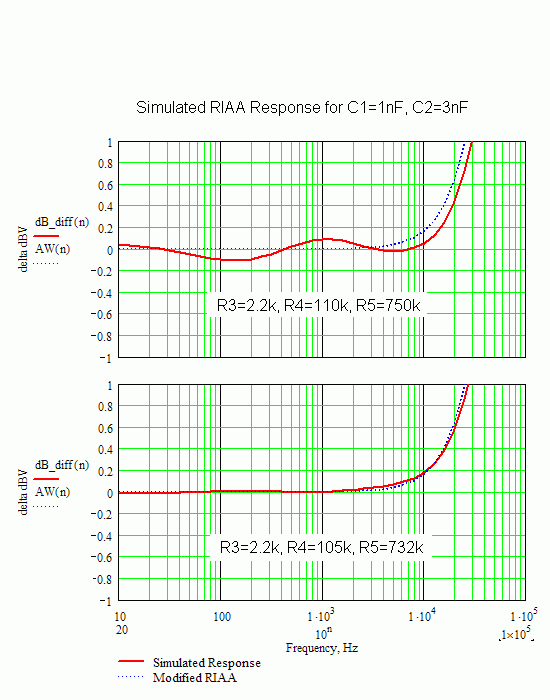
As seen in the simulation, the Allen Wright modification boosts the treble by 0.5 dB at 20 kHz, a modest change by any measure (blue trace). The VSPS follows this modified response (red trace).
Power Supply
The VSPS is best used with an external unregulated power supply:
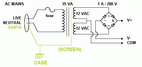
The transformer should have two 12 VAC secondary windings. A good basic choice is a 35 VA toroid, e.g. Talema 62072 (Digikey part no. TE62072-ND). Large toroidal or R-core transformers 100 VA or more are recommended for improved performance, e.g. Plitron. Much of the quality of the sound depends on the power transformer, so don't skimp on this part just because the current demands are only a few milliamps. Rectifying diodes (200 V / 1 A or larger) and a fuse rounds out the required componentry. Two power supplies can be used for true dual mono operation.
Voltage Regulation
The voltage regulation circuit including the filtering and bypass capacitors are normally all placed as close to the VSPS circuit as possible. The simplest version consists of fixed voltage 3-pin regulators, e.g. LM7812 and LM7912, with electrolytic capacitors on the inputs and outputs. The input capacitors are around 220 µF to 1000 µF, while the output capacitors should be smaller, typically 220 µF or less. Make sure the voltage rating is 25 V or higher.
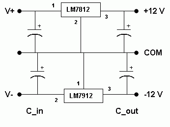
Adjustable regulators can be used instead for improved performance.
Layout
Printed circuit boards are available for both stereo and dual-mono versions.
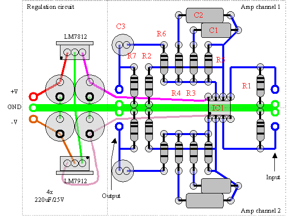
Below is an example layout for a basic stereo version using a dual op-amp (NE5532, OPA2134). Since this is a "beginners" project I have drawn it with more detail than normal. All parts and distances are nearly to scale. (Note: C2 is now a bank of three rather than the single capacitor shown.) The circuit can be mounted on a project board and point-to-point soldered using 24 gauge copper wire to connect the components.
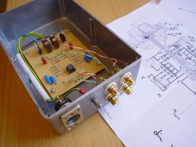
In the photo, the board is mounted in a Hammond aluminum project box, with an external power supply connected via a 3-pin XLR jack.
Construction
Please see the Construction Guide for additional hints and tips for building this project.
rjm003.geo at yahoo.com

|
