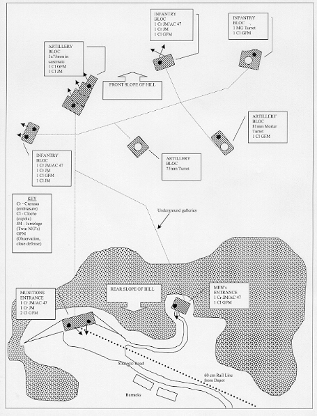
A typical large fortress (gros ouvrage) consisted of: casemates, cupolas, turrets, underground rail, power plants, munitions storage, and barracks. Casemates contained loopholes for infantry arms, or embrasures for artillery. Where artillery fired out of an embrasure, rather than from a roof turret, it was said to be "in casemate." Casemates provided mainly flanking fire in a 45-degree horizontal arc. The fa�ade was protected against artillery shots by an orillon, or overhang, on the enemy side. A deep ditch protected the embrasures and loopholes from explosive attacks and assured that the debris from the shelling did not obstruct the field of fire. There were machine-gun casemates, 75mm casemates with 2 to 3 guns each, and, more rarely, casemates for 135mm bomb throwers and 81mm mortars.

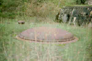
Fixed cupolas were domes made of molded steel, pierced by loopholes and sealed in the concrete roof of the casemate. The majority were used for signalling, or for riflemen and were known as GFM cupolas for Guetteur-Fusil-Mitrailleur (spotter-automatic rifleman). They permitted surveillance and observation with periscopes and diascopes, the defense of the top of casemates and the rear area, and to fire flare guns. It was customary for each block to have an observation cupola. Finally, there were small ventilation cupolas called mushrooms.
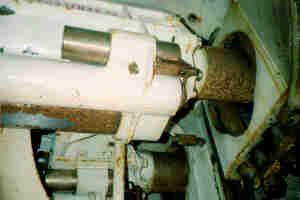 Turrets revolved 360 degrees and rose up or down to a height of about
1 foot above the roof surface of the block. A steel collar surrounded
the turret and provided further protection. The armament itself was
encased in a special steel dome to protect the gunners (2-4) and the
guns underneath. Artillery turrets were built in one piece and were
extremely elaborate. Each turret structure was about three stories
high. Protruding from the roof of the concrete block was a round,
low-angled dome about 4 feet in diameter. This was surrounded by a
steel collar, which was fixed into the concrete. If the turret were
raised, an observer could see two horizontal holes, about 2 feet
apart, half-way up the outer surface. These were the gun barrels
and there were two guns per turret. Underneath the steel dome was
the firing chamber.
A 75mm firing chamber was just barely high enough for a man to stand and wide enough to reach out and touch both sides of the circular walls. Most of the space was taken up by the two guns, which sat on carriages. Shells were sent up to the guns from below by hoist. The shell was then be loaded into the breech and fired. Once it was fired, the shell was ejected from the breech and fell into a container connected to a tube where it was finally ejected onto the floor at the bottom of the block, at the tunnel level.
 The machinery that operated the turret was below the firing chamber.
The turret was controlled either electrically, or manually using a
series of wheels and levers. From this level the turret could be
raised or lowered, pointed in a specific direction, or the guns could
be raised or lowered to the correct firing angle. Just below the
firing chamber floor, at head height and fixed to the circular outer
wall, was a metal band about 3 inches wide,.and etched with numbers
that indicated zero to 360 degrees. This served as the direction
finder. A small pointer attached to the turret would spin on the
inside of this band and would be turned until the turret was facing
in the proper direction.
A typical fortress, had two entrances, one for the troops, called the Entr�e d'Hommes (Men's Entrance), and the Entr�e de Munitions (Munitions Entrance). These were located to the rear of the combat blocks, deep in a wooded ravine on the reverse slope of the hill. The men's entrance was actually only used for ventilation purposes. All other movement was into the munitions entrance. Each entrance was well-protected by anti-tank weapons and anti-tank cannons pointed at the access road.
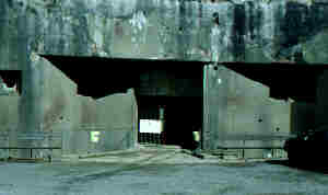 Entering through the munitions entrance, one encounters a long
concrete gallery which could accomodate a truck. The exterior was
protected by a ditch approximately 12 feet deep, which ran along the
facade of the outer wall. A bridge ran across the ditch to the
entryway. Firing chambers on the left and right of the entryway
guarded the entrance and the approaches. From the outside, the only
thing that showed were gun embrasures, and the barrel of the anti-tank
cannon or machine-gun. The interior entryway had several defensive
features: an iron gate, a ditch covered by a rolling bridge that
could be rolled away into a chamber on the other side of the interior
wall, leaving a large ditch over which a vehicle could not pass,
armored doors a foot thick, and interior blockhouses sited on the
entrance, about 35m back. Beyond the first blockhouse the concrete
is replaced with masonry, as the natural protection of the earth was
sufficient at this depth.
Beyond the entrance gallery, the main gallery was equipped with a 60cm electrified train track. To the left, the main gallery branched off to the men's entrance. This part of the fort was known as the caserne and contained the infirmary with showers for poison gas decontamination, sleeping chambers, lavatories, and police station, kitchens and storerooms. This area also housed the heart of the fort, the electric powerhouse, as well as the gas neutralization chambers. All of this was 35m underground.
 Electrical current from the powerhouse was needed for heating and
lighting, ventilation, elevators, turrets, radio stations, electric
kitchens, and munitions ramps. The current normally came from the
rear of the fort, from the national grid, and was connected by
underground cables to a nearby concrete-protected transformer station,
then through high-tension cables to the fort. A generating station
inside the fortress provided power in case of rupture from the outside,
consisting of four electrogenerator groups of Sulzer diesel motors,
each 290 horsepower and 250 kilowatts. They were powered by diesel
fuel stored in six reservoirs which would last two to three months,
plus a reservoir for lubricant. Chambers adjacent to the powerhouse
held eight reservoirs which could hold a total of 400 cubic meters of
fresh water, auxilliary generators to assure lighting in the
powerhouse, ventilators and pumps for fresh air, transformers to
power the substations in the combat blocks, and a substation to power
the train tracks wth continuous current.
The fort was provided with a ventilation and gas protection system in case of a World War I-style gas attack. In case of such an attack, ventilators would cause air overpressure to blow the air out of the fort. Ventilators also cleaned the air of gunpowder smoke and exhaust from the diesel engines. To prevent the total depletion of the air supply, air would be pumped from the outside, through round air filters about the size of a washing machine.
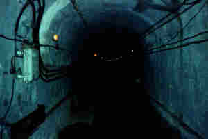 After the left branch to the caserne, the gallery continued to the
combat blocks and the command post, the brain of the fortress. The
gallery widened at certain places to permit two trains to pass each
other. The front part of the fort was protected by a second armored
door and by mines on each side of the gallery which could be detonated
to close off the tunnel. In this manner, if the enemy were to
penetrate past the entrance defenses into the galleries, the tunnel
leading to the combat blocks could be destroyed, preventing the enemy
from reaching the nerve center of the fort, and at the same time,
allowing the combat blocks to continue fighting. Past the second
armored door, the gallery branches off to the different combat blocks.
The length of the gallery from the entrance to the furthest
combat blocks could be as much as several kilometers.
A typical combat bloc could fire three tons of shells per minute. An elaborate transportation system was necessary to keep the guns replenished. Because of the destruction of the magazine of Liege's Fort Loncin in August 1914, the designers decided to maintain three types of munitions storage areas rather than one central magazine. By the munitions entrance was the main storage area between the outside and the blocks, known as M1. It had seven chambers, each 5 by 25 meters, which were isolated from the men's entrance and the caserne area. At the foot of each combat block, 20m below ground, was M2, with stores enough for two days of battle. In the block itself, near the weapons, was M3. For one 75mm cannon, M1 held 3,000 shells, M2 2,800, and M3 600. They were transported by locomotives of 5.5 tons along the 600-volt railways. A typical large ouvrage had four Vetra locomotives and 57 wagonettes, commonly called the "metro."
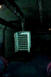 Shells were transported in containers called chassis from the
munitions depots on 60cm railway systems. A chassis was a metal box
that held around 100 75mm shells in racks and was the size of a small
refrigerator. The train from the depot entered the munitions entrance
and travelled along the gallery to a location known as the gare, or
train station. The chassis was moved to another wagonette pulled by
a small locomotive and transported to M1 or to the combat block's M2
magazine. Chains connected to pulleys on overhead rails were hooked
to the top of the chassis, which was hoisted out of the wagonette,
and pushed by hand along the rails into M2. To replenish the gun, the
chassis was again pushed along a rail and transferred to a rail in
the roof of the elevator leading up to the combat block. The elevator
rose to the gun level, the door was opened, and the chassis moved onto
rails in the ceiling of the surface block to the M3 storage area near
the base of the gun.
Telephone communications throughout the fort were handled by a telephone switchboard located in the command post near the combat blocks. This switchboard was connected to the outside system by underground cable. All the combat blocks were connected to each other and to the command post, storage depots behind the lines, and to reinforcements, as well as to all observation posts. This system allowed the guns to fire just three minutes after spotting a target by an observer. The fort was equipped with a transmitter-receiver and an outside antenna if the telephone service was cut.
In time of war, the garrison was manned by 812 men: 27 officers, 97 NCOs, 107 Corporals, and 587 soldiers, plus 161 engineers. Beds were available for those who were off duty. The fortress was set up like a ship, where the number of beds was less than the number of occupants. In Simserhof there were 509 beds for 812 men. There was plenty of water and chemicals for the toilets. Although conditions were not great, they were better than the trenches, or the forts of Verdun and Li�ge.
Operations inside the forts were an exact science. Three fortresses were linked to form an artillery group under the control of a sub-sector artillery commander. This would enable one fort to support the other and for massed battery fire to be easily coordinated.
The Maginot Line is not responsible for content of this banner