Al's earthquake damage magnitudes
Small earthquakes
A small earthquake is considered to have a low peak ground acceleration and short duration. No structural damage from a small earthquake should occur but only to a poorly designed or constructed building where cracks in
the facade or some windows are broken. Non-structural damage should be to the contents such as glass falling from the shelves, etc.
(MM scale of I to IV)
Medium earthquakes
A medium earthquake is considered to have a moderate peak ground acceleration and short to medium time duration. Both the Northridge and Loma Pierta earthquake fall into this category. Structural damage will occur to a poorly design or constructed buildings. Very minor structural damage may occur in a medium to well designed buildings. Some architectural, mechanical, and electrical damage may occur in all cases depending on the design and construction.
(MM scale V to VII)
Large Earthquakes
A large earthquake has a large peak ground acceleration with a long duration. The Kobe earthquake meets this criterion. There will be both structural and nonstructural damage in the majority of the buildings. The extent will depend on the structural design. Some of the poorly designed and constructed buildings will probable collapse or partially collapse.
(MM scale VIII to IX)
Great earthquakes
The great earthquake can be considered a 100-year event with a very large ground acceleration that appears to last for eternity. I believe the 1964 Anchorage earthquake fit this type of earthquake. There will be significant structural and nonstructural damage to all buildings. Even the well design and built buildings will have damage. There will be buildings that will collapse or partially collapse.
(MM scale X to XII)
MM scale is the Modified Mercalli scale which is more descriptive and better defines the earthquake damage then the Richter scale.
Building Seismic Performance Levels
Collapse
No Collapse
but Major structural and major non-structural damage
Minor Structural damage and major non-structural damage
No structural damage and very minimal non-structural damage
No damage
Given the Al's earthquake magitude and buiding seismic performance levels, A matrix of damage verses earthquakw size can be developed. Eventually, there will be a matrix for different level of design on this site.
|
 MOMENT
FRAME |
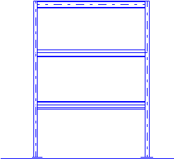
Moment frame in Steel
Steel moment frames are very flexible lateral elements, such that, the expected nonstructural damage may be intolerable to the building owner. Therefore, moment frame buildings should be designed with a very low drift. First, this can be accomplished by providing a very large number of frame lines. Secondly, provide large column sections and medium beam sections. An engineer should always consider strong column and weak column configurations and P-delta effects. Third, always consider that in a large earthquake that the moment frames will go into the inelastic range. Therefore, the moment frame will be pushed further and the corresponding drift will be quite huge. For this reason, moment frames should never be designed for stress only. If moment frames are designed for stress, the moment frames will be too flexible that the damage to the building will be too great for a moderate earthquake and for a great earthquake and there is the possibility of collapse.
|
 ECCENTRIC BRACED FRAME |
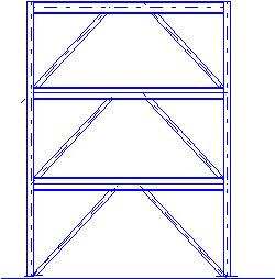
Eccentric Brace Frames
There are three components to the lateral deflection of a building using an EBF lateral load carrying system. First is the lateral displacement due to the beam rotation of the link beam. Secondly, there is the axial deformation of the brace and third, the axial deformation of the column. The link beam rotation should account for most of the lateral deflection and the brace and column axial should account for remaining portion. It is imperative that the brace is stronger than the link beam and the column does not fail under any circumstances. Therefore, the column should be over-designed. One of the problems with EBF system is the number of link beams in a building. If there is too few or the load to each link beam is high, then is highly recommended that a supplemental back-up moment frame be used. Now that the Northridge earthquake showed the poor performance of the beam to column connection, there is only two basic EBF configurations, the chevron type configuration and the inverted V shape configuration with the link beam in the center of the bay.
|
 CONCENTRIC BRACED FRAME |
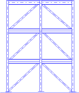
Concentric Brace Frames
All CBF's should meet the requirements of a special CBF where there is a yielding mechanism in the brace. I recommend the brace connection to be able to accept some ability to buckle. Chevron braced frames or similar shall be outlawed. Under severe seismic loads they will pull down the floor beam causing some local collapse. CBF columns shall be over designed so they never collapse under any seismic conditions.
Most of the concentric braced frames are designed with a fix end brace connection where the brace is knifed into the gusset plate. the result is that in a severe earthquake the end connection will be severely damage requiring substantial repair work. The alternate is to provide a yielding mechanism at the end that allows for bending of the brace and the brace buckles at the center. The repair work will consists of replacing the brace.
As with EBF's, the number of braced frames in the building is a problem. If there are too few or the tributary load is quite high, it is recommended to add a backup moment frame. This backup moment frame should be designed to be stiff enough to be effective before the compression braces buckles. This means the moment frame will be quite heavy since CBF's are quite stiff systems.
|
CONCRETE SHEAR WALL |
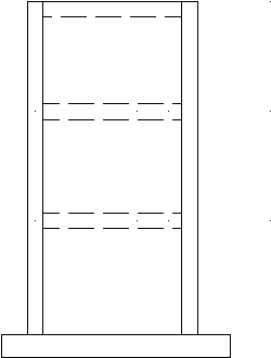
Concrete Shear Walls
For shear walls with height to length ratio
greater than one, concrete shear shall be designed for flexure yielding before shear yielding. In other words, the concrete shear wall shall not fail in shear. Therefore, Al's
rule of thumb is to size the shear wall for an ultimate demand shear stress of approximately equal to the capacity of the concrete only and provided a total capacity of concrete and reinforcing steel of a minimum of several times that value.. All boundary elements shall be confined and will have appropriate amount of boundary steel that provided a shear capacity greater than that the wall bending capacity.
|
 COUPLED SHEAR
WALL |
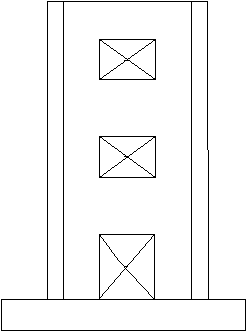
Coupled Concrete Shear Walls
Coupled concrete shear walls are a large concrete frame with deep columns and large beams. There are high axial loads on each pier either tension or compression with a moderate bending moment. The entire lateral load must be taken by the deep column piers. Each end of the column pier shall have a confined core with the outer end being the large and taken the largest axial load. The interior cores are needed at the boundary end of the window or door and must be aligned full height. The coupling beam shall be design not only a tension member but as a confined concrete column spanning diagonally between the column piers.
This column must be larger than the tensile capacity. The yielding mechanism in the beam is the diagonal tension reinforcing. The anchorage of the tensile reinforcing shall be as far into the column, consider the column in tension on one side. The remainder of the reinforcing in the coupling beam is very nominal reinforcing, such that, there is a minimal increase to the coupling beam capacity. The overall wall piers shall have a shear capacity greater than the coupling beam capacity. The coupling beams should yield before the wall piers yield in shear.
|
 BASE
ISOLATION W/ CBF ABOVE |
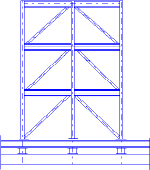
Base Isolation System
Base isolation systems are a secondary lateral system that dissipates much of the seismic energy from the building main lateral system. A non base isolated building primarily lateral system will see a very large ground acceleration, such that, these elements will go into the inelastic range. A base isolated building primarily lateral system will never reach that level. The problem with a base isolated building are there needs to be one additional diaphragm or floor in the building and this adds considerable cost to the building. An example is the foundation system consisting of
spread footings with grade beams below the isolators and a first floor framing above the isolators. There also needs to some type of future jacking concept in the design of the building. An some authorities will request a secondary skid or support system. Another problem with a base isolated building is the amount of movement at the isolators can be up to 24 inches or more. This can be a problem in largely dense areas where buildings tend to
abut each other. There are other problems with base isolated buildings;
 Soft soils may have periods close to the building with isolators negating any benefits of the isolators Soft soils may have periods close to the building with isolators negating any benefits of the isolators
 Building above the isolators should never have a period close to the Isolator period Building above the isolators should never have a period close to the Isolator period
|
| Disclaimer
All information, opinions, comments, etc, expressed on this web page are this structural engineer's professional opinions, comments, etc. and are not intended to harm any other engineer's
professional opinion, comments, buildings or projects.
|
|
The best solution for seismic resisting systems is to have an energy dissipating mechanism that can be cheap to replace after being damage in a large or great earthquake. These systems can be high tech or a simple design and detailing of a regular seismic system. |
AL WHITECAR STRUCTURAL ENGINEER |
 Click on the spinning ball for more Seismic Resisting Systems Click on the spinning ball for more Seismic Resisting Systems
|
SEISMIC RESISTING SYSTEMS |
| DRAWN BY AL WHITECAR |
| Copyright Al Whitecar structural engineer 1999, free graphic images obtained from many sites thanks |
MARCH 1999 |
S-3 |

