About the Efficiency of the Regenerator in the Stirling Engine
and the Function of the Volume Ratio V max / V min
Dipl.-Ing. Peter Fette
Am Schaeferloch 16,
D-75045 Walzbachtal / Germany
ABSTRACT:
Attention: some browsers may not produce correct greek letters but show them as latin equivalents
The twice double
acting Stirling Engine introduced at the 6'th International Stirling
Engine Conference ISEC at Eindhoven Netherlands in May 1993 (Report
No. ISEC-93003) is an engine which can realize realative high volume
ratios V max / V min . Whenever a heatsource and a
cooling water supply and their corresponding haetexchangers have
enough power for the energy transmission then a higher volume ratio
of V max / V min will lead to a higher work
output per revolution. Theoretical work is done with regard to the
efficiency of the regenerator, the volume ratio of the engine and the
adiabate exponent k = Cp / Cv
of the working fluid. It can be shown, that the efficiency of the
regenerator can be lowered for the benefit of a lower loss of
pressure in it. For very high volume ratios the regenerator can be a
suitable tube only. Formulas and diagrams
illustrate the correlation
of Carnot efficiency and the thermal efficiency of the process with
the parameters: volume ratio Vmax/V min,
k
and the regenerator efficiency
hreg .
All diagrams and calculationen were made with the program
STMOT2 |6|, base of this program is described in
|7|
Nonenclature:
The theoretical considerations of Finkelstein |2| were a challenge to make further theoretical and practical investigations for the Stirling engine decribed in |1|. So this theoretical work is specially done for this engine. The results may not be transfered in all consequences to other Stirling engines, but the tendency of these results should be valid for other engines too.
In the engine |1| a change of the volume ratio is easy to be performed by variation of the working liquid within the cylinders below the gas cushion. Insofar this engine is an optimal testengine too. There are some reasons that a regenerator for this Stirling engine cannot be optimally designed in the common way. E.g. because of too much loss of pressure in the regenerator, and, for this engine is able to work with compound fluids, a commonly designed regenerator will not work with condensating steam, it has additional disadvantages too. A regenerator designed for this engine will work at a loss! But the questions to be answered are: What a loss at the regenerator is tolerable, and what can we do to increase the thermal efficiency with others than an optimal commonly designed regenerator?
These are the common questions. There have been done a lot of theoretical invetigations on this territory, some described in |3|. This work will not only add one more, but it makes an attempt to give an other point of view to these questions, naturally with special attention to the engine of |1| for heatsources of low to medium temperatures.
Going out from an ideal isothermal Stirling process we introduce the effectiveness of the regenerator to this process and then call this process the "disidealized" isothermal Stirling process having a variable efficiency of the regenerator |5|.
The thermal efficiency of a process is defined as the ratio between "W" the external work done per cycle and "Qext" the external heat supplied per cycle to the engine.
(1) ![]()
Concerning all phases the efficiency of the ideal Stirling process is:
(2) 
In this ideal Stirling process it is
supposed, the regenerator is of 100 %
efficiency; hreg
= 1 . Then the isochoric heat supplied by the
regenerator
Q2 - 3 at constant
volume V min is equivalent to the isochoric heat Q 4 - 1 that is received by the regenerator
at constant volume Vmax.
So Q 2 - 3 +
Q4 - 1 = 0. and the external supplied heat
for the ideal process is: Qext = Q3 - 4
. Now the ideal efficiency is:
(3) 
Imagine a disidealized Stirling process with a regenerator at a loss. h reg < 1 . We define a lossfactor RV = 1 - h reg .
Now imagine that the work "W" done per cycle should be the same for the ideal as for the disidealized process. Then for the case of hreg < 1 additional heat must be supplied by the heater to get the temperature "TE" at the end of the isochoric change of state done by the regenerator and before beginning the isothermal expansion. And at the other isochoric change of state, -cooling done by the regenerator- additional heat must be rejected by the cooler to get the temperature "TC" before beginning the isothermal compression phase at Vmax. This part of the energy which the regenerator cannot supply to the process may be defined as Q reg = RV * Q2-3
With these considerations we now define a thermal efficiency of the disidealized process:(4) 
We now must get this equation in a suitable form by evaluating the above expressions: Q 3 - 4 the heat supplied at the isothermal expansion phase is equal to the external work done during isothermal expansion:
(5) 
for the compression phase:
(6) 

The isochoric heat supplied at Vmin is:
(7) ![]()
We now get for h therm
(8) 
We make further substitutions:
Carnot efficiency
h C = ( TE - TC) / TE .
The adiabate exponent
k = C p/ C v
and the gas constant R = C p - Cv
leads to the term
C v / R = 1 / (k - 1).
We now get h therm in the wanted form for computer calculations:
(9) 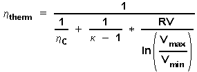
The meaning of equation (9) is:
The resulting thermal efficiency of a disidealized Stirling process -that is an isothermal Stirling process with a regenerator at a loss of RV= 1 - h reg - is a function of:
- k = 1.6 for one-atomic gases like Helium, Argon,
- k = 1.4 for two-atomic gases like Hydrogen, Air,
- k = 1.3 for three-atomic gases like Carbondioxyd CO 2
Fig. 1 represents the calculation of Equation (9) for 5 different volume ratios:
The abszissa in this diagram is the Carnot efficiency in the range
from 5 <= h c
<= 80%. The ordinate is the resulting thermal efficiency
according to equation (9).
The drawn example in
Fig. 1 says: If You know the
temperatures "TE" and "TC" of a disidealized
Stirling process, which in this example will lead to a Carnot
efficiency of 28% and You have a volume ratio of V max
/ Vmin = 1.6 in Your engine which is
working with a regenerator at a loss of RV = 50 % then You will get a
resulting thermal efficiency of this process of
htherm = 16 %.
A second result of
this example is: You will get the same efficiency of h therm
= 16 % if You have only a tube, a regenerator
with h reg
= 0 , and when You design this engine with a
volume ratio of Vmax /Vmin = 2.5 .
Fig. 2
shows the dependency of the working fluids characteristics
k = C p/ Cv
. These regenerator
efficiencies are specially choosen to demonstrate, that You will get
the same thermal efficiency now with the same volume ratio in the
engine but with a worse regenerator if You choose Helium or Argon
instead of air as the working fluid. This result of
equation (9) is to be taken with care, because if You change the
working fluid, equation (9) does not take into account the thermal
conductivity of the working fluid, which is also important for the
efficiency of the process. But on the other hand if You design a slow
rotating engine as described in |1| with an optimal heattransfer to
the working fluid, Argon will be the better working fluid than air
inspite of its slightly worse thermal conductivity. (Naturally the
more expensive inert gas Helium is the best for its thermal conductivity
is atleast 4 times better than that of air !)
For the engine
described in |1| a FORTRAN 77 computer program STMOT2 |6| is
develloped for the calculation and graphical output of several 100
functions of interrest.
In Fig.3 the working fluid is Air with k = 1.4 , and
In Fig.4 the working fluid is Argon with k = 1.6 .
(10) 
The "frames" in both T-S diagrams represent the ideal isothermal Stirling process, the graph within the frame is the calculated T-S diagram of the real process of this a - type engine |1| driven by a crankgear. In both cases the included area of the graphs represent the same external work done per cycle. Have a look to the different gradients d T/d S of these "frames" which are borders of the isochoric heat.
The isochoric heat exchanged by the regenerator is much less at the "frame" in Fig.4 (Argon) than in Fig.3 with air as the working fluid.
The thermal efficiency htherm of the "calculated real process" is improved from h therm = 20.6 % in the case of the working fluid is Air to h therm = 23.7 % in the case of Argon.
According to equation (9) the thermal efficiency h therm of the "disidealized" isothermal process -the "frames" in Fig. 3 and Fig. 4- is improved from h therm = 25.6 % in the case of the working fluid is Air to h therm = 29.1 % in the case of Argon.
The calculations |6| of the processes in Fig.3 and Fig.4 are both done with:
There are made 8 additional simulation runs with the computerprogramm STMOT2 to demonstrate the influence oft the idle pressure P0 (this is the gas pressure within the resting and cold engine), the volumeratio V max / V min, the adiabatic exponent k and the regenerator efficiency hreg to the usable power and the usable efficiency h_n of the engine. These results are presented in a table (Some more information to the output of STMOT2 see in |6|. The input datasets for these 8 simulations are described in section "5 of sample calculations" . The reader may copy the input data from here to make his own calculations with STMOT2)
All values of interest in the table for the working fluid Helium are marked red and are marked blue for the fluid air. Some more remarks are to be made:
In column 1 of the table
RUN NO. points to the No. of the simulation run.
In column 7 : ETA_R
is the regenerator efficiency hreg
In column 9 : P0
is the idle pressure P0 of the resting and cold engine;
P1MEAN is the mean working pressure.
In column 10 : Vmax/Vmin is the volume ratio
In column 13 : ETA_N is the usable efficiency,
which is written h_n in the signatures to Fig.(1)(2) and Fig.(5)(6).
In column 15 : POWER USABLE
is the mean usable power for the calculated revolution.
In column 16 : DQZU1 MAX
is the maximum of the graph for the supplied heat at this revolution.
You will find more information to this table output in chapter I.6.2 of the user guide to
STMOT2 (in german only).
The first 4 simulation runs concern the increase of usable power "POWER USABLE" as a reaction of the higher volumen ratio; run No (1) and run No (2) are calculated for air with a k = 1.4 and run No (3) and run No(4) are calculated for Helium with a k = 1.6 . Here a short extract from the table
The strong increase of power from POWER = 343 Watt in simulation runs No. (2) and (4) to POWER = 1637 Watt in runs No (1) and (3) naturally is only obtained when "heater" and "cooler" can perform the needed high energy transmissions !! The maximum values for the heat supplied "DQZU1 MAX" are in column 16: of the table. For Helium as the working fluid a smaller maximum value "DQZU1 MAX" is calculated as it is to be expeted in accordance with equation (9).
Fig.(1)(2) shows as functions of the crank angle the graphs for: supplied heat "DQZU1", the removed energy "DQAB1", the idle pressure P1 and the mean power for the calculated revolution "POWERN". Here all graphs of runs No (1) and (2) with air as the workind fluid are put together in 1 diagram. The signals (1) and (2) in Fig.(1)(2) are in accordance with these run No's. 1 and 2 of the table. The values for Helium are shown in the table at RUN NO. 3 and 4.
In the next 4 simulation runs (5) and (6) with air and runs (7) and (8) with Helium the usable power of the engine shall be hold constant at 316 to 319 Watt. It shall be shown here, that this power can be reached with a high volume ratio Vmax/Vmin = 2.71 at a significant lower idle pressure "P0"= 3.3 bar (or a significant lower mean pressure "P1MEAN") and at a lower regenerator efficiency hreg= 40 %, than the same power is obtained with a lower volume ratio Vmax/Vmin = 1.29 but with P0=15 bar and hreg = 80%. Next to this, the simulation shows the maximum point for the heat supplied "DQZU1_MAX" is significant lower, when the engine works with this high volume ratio at this power of 316 - 319 Watt. Here again a short extract from the table
These simulation results seem to be impossible on the first view. A good way to explain this phenomenon of the results of runs no.
(5) and (6) for air as the working fluid will give the T-S Diagrams in Fig.(5)(6)TS, and for the runs
(7) and (8) with Helium the
T-S Diagrams in Fig.(7)(8)TS will give an explanation:
The work done per revolution, is represented by the area included by the graphs in these diagrams. This work minus the friction losses result in the POWER USABLE: 316 resp. 319 Watt. The areas included by the
"frames" around the graphs, are equivalent to the work of the ideal Stirling process. If we now look to the ideal Stirling processes for the simulation runs (5) and (6) (or to the runs
(7) and (8)), then indeed we find a quite other result. The work done "Wi" of the ideal Stirling process is equal to the numerator in eq.(8) -see obove:
Wi = M Gas * R * (TE - TC) * ln ( V max / V min )
here the gasmass "M Gas" is proportional to the idle pressure P0. By this the work of the ideal Stirling processes from simulation run (6) with the high idle pressure P0 = 15 bar is significant higher as in run no. (5) where P0 = 3.3 bar. You easy will see, when comparing the "frames" in both diagrams of Fig.(5)(6)TS (and in both diagrams of Fig.(7)(8)TS). The ideal Stirling process does'nt know deadspaces, the real Stirling process, in which acts a continuously working crank gear, must consider the deadspaces. Now in the real Stirling process a high volume ratio -this means small deadspace- results in a high "load exploitation factor" -here 37.11% of the ideal Stirling process is reached. (for the "load exploitation factor" also look to my unshortened report to the 6#th ISEC in Eindhoven |1|.) The large deads pace, which is defined in the input data to simulation runs no. (6) and (8), here now leads to a smaller load exploitation factor -here 8.73% of the maximal possible -the ideal- process, so you will only get nearly the same work done inspite of the higher mean pressure resp. the higher idle pressure P0 as in runs no. (5) and (7). In column 13 of the table values for AUSN_I are these load exploitation factors.
The total gasmass in run no. (5) is GM01= 1.394851 gr air. This is a significant lower gasmass in the engine as in run no. (6) where the total gasmass is GM01= 23.520571 gr air (see below columns 17 to 19 in theTabelle). Therefore heat to be supplied to warm up the gasmass in run no. (5) will be much more lower. The maximal supplied heat you find in column 16 of the table with a value of "DQZU1_MAX" = 2496 Watt, and for the run no. (6) the maximal heat supplied is "DQZU1_MAX" = 5266 Watt.
Like Fig.(1)(2) now the Fig.(5)(6) shows as functions of the crank angle the graphs for: supplied heat "DQZU1", the removed energy "DQAB1", the idle pressure P1 and the mean power for the calculated revolution "POWERN". Here all graphs of runs No (5) and (6) with air as the working fluid are put together in this 1 diagram. The signals (5) and (6) in Fig.(1)(2) are in accordance with these run No's. 5 and 6 of the table. The values for Helium are shown in the table at RUN NO. 7 and 8.
The usable efficiency ETA_N in column 13 of the table is written in Fig.(1)(2) and Fig.(5)(6) with "h_n". These values can also be found for the Fig.(5)(6) at the RUN NO. (5) and (6) in the table. Please notice the usable efficiency h_n = 19.59 % in RUN NO. 5 is a bit higher than in RUN NO. 6 where h_n = 17.89 % inspite of a higher regenerator efficiency in RUN NO 6. Here hreg= 40 % is half as large as hreg= 80 % in RUN NO 6.
(The usable efficiency "h_n" and the usable power "POWERN" take into account the mechanical friction losses of the engine. Therefore "h_n" is less than htherm.)
Conclusion:
Each Stirling engine is wanted to have a high ratio h therm / h C ; this is specially wanted for those engines which are working with low to medium temperatures. The regenerator of the engine|1| will work at a loss, when it should be designed for working with compound fluids. One possibility of equalizing the regenerators loss in double acting engines is to design it as a counterflow heatexchanger as described in |1|.
A further improvement for a better h therm is got by a higher volume ratio Vmax / Vmin. This additionally can be achieved by following the rules in |2| with the ratio of the stroke volumes in expansion and compression spaces made equal to their temperature ratio: VE/VC = TE/TC. See the section "4 of sample calculations". (Raising the volume ratio Vmax /Vmin at least is limited by the effectiveness of the heatexchangers!)
A third but simple improvement will be to choose an one atomic inert gas rather than a two (or three)- atomic gas as the working fluid. (If in this sense Helium will be better than Hydrogen -with its twice better thermal conductivity than Helium- is to be tested; but Argon should be better in this sense than air.)
Equation (9) is derived from a "disidealized" Stirling process with isochoric heat transmission at a constant volume. Concerning h therm, Vmax/Vmin and k the calculations of the crankgear driven engine |1| are similar to the results of equation (9), because of the prerequisites coming from this engine are more qualified for a comparisation of this process to the "disidealised" isothermal process than the more adiabatic processes of common Stirling engines:
A new point of view for the calculation of the heatprocess of this engine shall be discussed here:
An isothermal change of state is defined by :
![]()
An adiabate change of state is defined by :
![]()
A polytrope change of state is defined by :
![]() with the exponent n < k
with the exponent n < k
The change of state in this process |1| may be defined by
![]()
The exponent e is less than the exponent
for an adiabate or polytrope change of state. This, because the
heattransmission here is extremly forced during the expansion and
compression phase; insofar the changes of state in this process are
close to isothermal.
So the exponent e will
be 1 < e << n. It will be e nearly =1.
As a derivation of the above formula temperatures can be calculated
with:
(11)

An other assumption which is made when calculating this process is to have the same instantaneous pressure in all spaces |4|. With these assumptions the above mentioned similar results for the "disidealised" and the nearly isothermal process of the engine |1| are obtained.
Literature:
|1| P.Fette: A Stirling Engine Able to Work with Compound Fluids Using Heat Energy of Low to Medium Temperatures. Presented at the 6'thISEC in Eindhoven 1993; ISEC-93-003. See also the report at this homepage.
|2| T. Finkelstein: Theoretical Considerations: The Concept of the"Cumulative Mass" and "Thermodynamic Mid-Plane" and the Resulting Volume Ratios, Europeen Stirling Forum Osnabrück 1994
|3| G. Walker: Stirling Engines, Clarendon Press Oxford 1980
|4| R.J.Meijers: Der Philips Stirlingmotor, Motoren Technische Zeitschrift MTZ 29(1968)/7, DK 621.41/43 (492) Philips
|5| P.Fette: Neuer Wärmekraftprozess für die Nutzung von Niedertemperatur Wärme, Brennstoff Wärme Kraft Bd.39 1987 Nr.11, VDI Verlag Düsseldorf
|6| P.Fette: STMOT2 ein FORTRAN 77 Computerprogramm für Studien des Stirlingprozesses
|7| P. Fette Grundlagen für die Berechnung des Wärmekraftprozesses und der Dynamik von a -Typ Stirlingmotoren mit dem Programm STMOT2
Fig.1 The Effect of V max / V min and the Regenerator efficiency hreg on the Thermal Efficiency htherm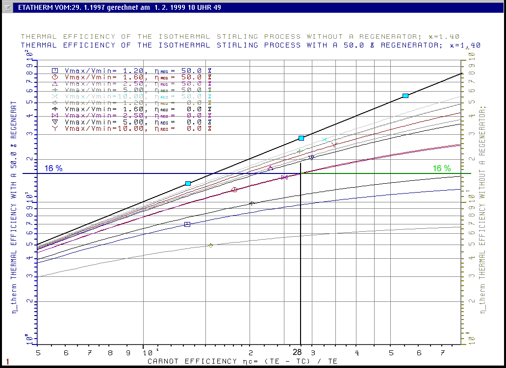
The upper black line with 3 blue rectangles stands for h reg = 100 % for all Vmax / Vmin and for all k's
press Your browsers Return button to return into previous text
Fig.2 The Effect of V max / V min and the Adiabatic exponent k = C p / C v on the Thermal Efficiency htherm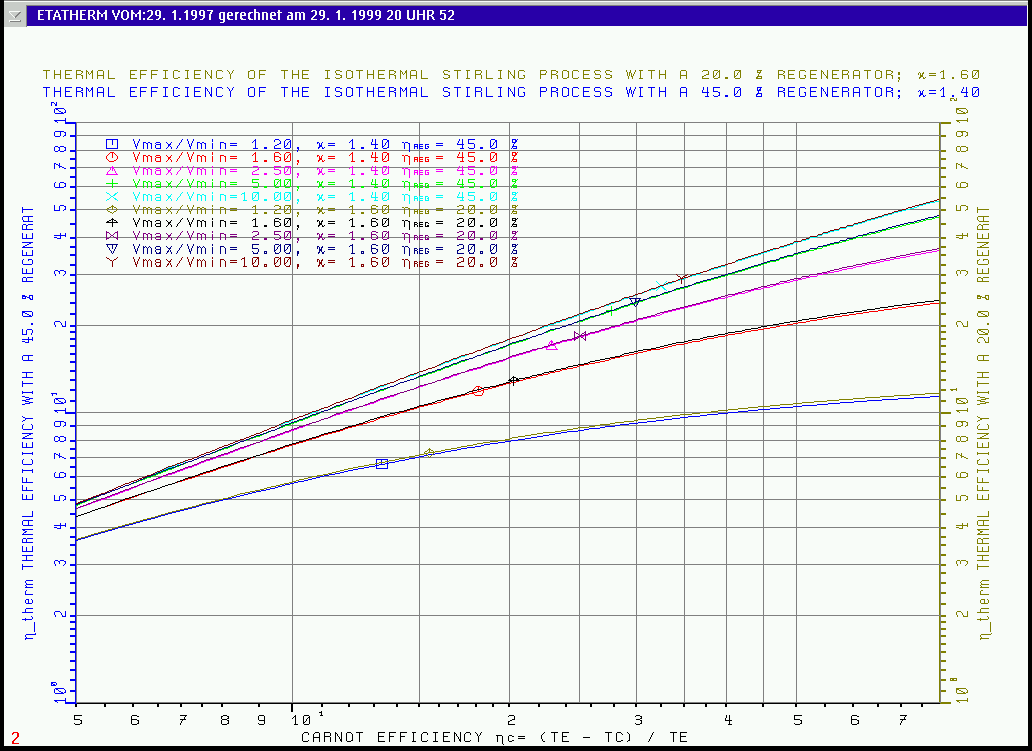
press Your browsers Return button to return into previous text
press Your browsers Return button to return into previous text
More significant than the Fig.(1)(2) and Fig.(5)(6) is the following table presenting the results of the 8 simulations. This table is made by the programm STMOT2.
____________________________________________________________________________________________________________________________________
  1 |  2  | 3  |  4   |  5   |  6   |  7   |  8   |  9   | 10  | 11  |  12   |  13   |  14  | 15  | 16  |  17  |  18  |  19  |  20
 ___|_____|____|______|______|______|______|______|______|_____|_____|_______|_______|______|_____|_____|______|______|______|______
 RUN| DKST|KAPA| TEMP.|STROKE| DEAD |REGEN.| DEAD |  P0  |VMAX |PMAX | WORK  | WORK  |- WORK|POWER|DQZU1|DIFFERENCE IN GASMAS|TIME .
 No.| DH  |EXP |  TH  | VOL. | VOL. | VOL. | VOL. |      |  /  |  /  |  A1   |  A2   |LOST  |USABL| MAX | EXP. | COMP.| REG. |  sec
    | DK  |COMP|  TK  | EXP. | EXP. |      | COMP.|      |VMIN |PMIN |       |Watt*s |      |     |     |      |      |      |
    STROKE|    |TE_MAX| COMP.|      |cm**3 |      |P1MEAN|     |     |       |       |      |     |     |      |      |      |REVOL.
 RE-|     |    |TC_MIN|      |      |      |      |      |     |     |       | ETA_N |      |     |     |      |      |      |TIME
 VOL|     |    |      |      |      | ETA_R|      |      |     |     |       | AUSN_I|      |     |     |      |      |      | msec
    |     |    |      |      |      |      |      |      |     |     |       | AREF_I|      |     |     |      |      |      |
    |cm   | -  |Kelvin|cm**3 |cm**3 |   %  |cm**3 | Bar  |  -  |  -  |Watt*s |   %   |Watt*s| Watt| Watt|Gramm |Gramm |Gramm |RPM
 ---|-----|----|------|------|------|------|------|------|-----|-----|-------|-------|------|-----|-----|------|------|------|------
   1| 2.00|1.00| 500.0| 251.3|  10.1| 100.0|  10.1|16.000|2.710|2.832|  156.8| 154.81|11.146| 1637| 9124| 3.504| 4.173| 2.177| 0.375
    | 8.00|1.00| 300.0| 235.6|      |      |      |      |     |     |       |       |      |     |     |      |      |      |
    | 8.00|    |      |      |      |      |      |      |     |     |       |30.46 %|      |     |     |      |      |      |  374.7
    | 5.00|    | 500.0|      |      |  80.0|      | 22.58|     |     |       |39.62 %|      |     |     |GM01=   6.762916 Gr |
   1|     |    | 300.0|      |      |      |      |      |     |     |       |22.40 %|      |     |     |TOTAL GASMASS       | 160.2
    |     |    |      |      |      |      |      |      |     |     |       |       |      |     |     |      |      |      |
 ___|_____|____|______|______|______|______|______|______|_____|_____|_______|_______|______|_____|_____|______|______|______|______
   2| 2.00|1.00| 500.0| 251.3| 502.7| 100.0| 502.7|16.000|1.290|1.297|   35.0|  34.84|11.144|  343| 5618| 3.061| 3.161| 0.465| 0.375
    | 8.00|1.00| 300.0| 235.6|      |      |      |      |     |     |       |       |      |     |     |      |      |      |
    | 8.00|    |      |      |      |      |      |      |     |     |       |17.99 %|      |     |     |      |      |      | 374.9
    | 5.00|    | 500.0|      |      |  80.0|      | 20.13|     |     |       | 8.78 %|      |     |     |GM01=  25.088609 Gr |
   1|     |    | 300.0|      |      |      |      |      |     |     |       | 1.27 %|      |     |     |TOTAL GASMASS       | 160.0
    |     |    |      |      |      |      |      |      |     |     |       |       |      |     |     |      |      |      |
 ___|_____|____|______|______|______|______|______|______|_____|_____|_______|_______|______|_____|_____|______|______|______|______
   3| 2.00|1.00| 500.0| 251.3|  10.1| 100.0|  10.1|16.000|2.710|2.832|  156.8| 154.81|11.146| 1637| 8598| 0.484| 0.576| 0.301| 0.375
    | 8.00|1.00| 300.0| 235.6|      |      |      |      |     |     |       |       |      |     |     |      |      |      |
    | 8.00|    |      |      |      |      |      |      |     |     |       |33.39 %|      |     |     |      |      |      | 374.7
    | 5.00|    | 500.0|      |      |  80.0|      | 22.58|     |     |       |39.62 %|      |     |     |GM01=   0.933516 Gr |
   1|     |    | 300.0|      |      |      |      |      |     |     |       |22.40 %|      |     |     |TOTAL GASMASS       | 160.2
    |     |    |      |      |      |      |      |      |     |     |       |       |      |     |     |      |      |      |
 ___|_____|____|______|______|______|______|______|______|_____|_____|_______|_______|______|_____|_____|______|______|______|______
   4| 2.00|1.00| 500.0| 251.3| 502.7| 100.0| 502.7|16.000|1.290|1.297|   35.0|  34.84|11.144|  343| 5308| 0.422| 0.436| 0.064| 0.375
    | 8.00|1.00| 300.0| 235.6|      |      |      |      |     |     |       |       |      |     |     |      |      |      |
    | 8.00|    |      |      |      |      |      |      |     |     |       |22.47 %|      |     |     |      |      |      | 374.9
    | 5.00|    | 500.0|      |      |  80.0|      | 20.13|     |     |       | 8.78 %|      |     |     |GM01=   3.463093 Gr |
   1|     |    | 300.0|      |      |      |      |      |     |     |       | 1.27 %|      |     |     |TOTAL GASMASS       | 160.0
    |     |    |      |      |      |      |      |      |     |     |       |       |      |     |     |      |      |
 ___|_____|____|______|______|______|______|______|______|_____|_____|_______|_______|______|_____|_____|______|______|______|______
   5| 2.00|1.00| 500.0| 251.3|  10.1| 100.0|  10.1| 3.300|2.710|2.841|   32.6|  32.14|11.144|  316| 2496| 0.725| 0.863| 0.448| 0.375
    | 8.00|1.00| 300.0| 235.6|      |      |      |      |     |     |       |       |      |     |     |      |      |      |
    | 8.00|    |      |      |      |      |      |      |     |     |       |19.59 %|      |     |     |      |      |      | 374.9
    | 5.00|    | 500.0|      |      |  40.0|      |  4.67|     |     |       |37.11 %|      |     |     |GM01=   1.394851 Gr |
   1|     |    | 300.0|      |      |      |      |      |     |     |       |20.98 %|      |     |     |TOTAL GASMASS       | 160.0
    |     |    |      |      |      |      |      |      |     |     |       |       |      |     |     |      |      |      |
 ___|_____|____|______|______|______|______|______|______|_____|_____|_______|_______|______|_____|_____|______|______|______|______
   6| 2.00|1.00| 500.0| 251.3| 502.7| 100.0| 502.7|15.000|1.290|1.297|   32.8|  32.66|11.144|  319| 5266| 2.869| 2.963| 0.436| 0.375
    | 8.00|1.00| 300.0| 235.6|      |      |      |      |     |     |       |       |      |     |     |      |      |      |
    | 8.00|    |      |      |      |      |      |      |     |     |       |17.89 %|      |     |     |      |      |      | 374.9
    | 5.00|    | 500.0|      |      |  80.0|      | 18.87|     |     |       | 8.73 %|      |     |     |GM01=  23.520571 Gr |
   1|     |    | 300.0|      |      |      |      |      |     |     |       | 1.26 %|      |     |     |TOTAL GASMASS       | 160.0
    |     |    |      |      |      |      |      |      |     |     |       |       |      |     |     |      |      |      |
 ___|_____|____|______|______|______|______|______|______|_____|_____|_______|_______|______|_____|_____|______|______|______|______
   7| 2.00|1.00| 500.0| 251.3|  10.1| 100.0|  10.1| 3.300|2.710|2.841|   32.6|  32.14|11.144|  316| 2135| 0.100| 0.119| 0.062| 0.375
    | 8.00|1.00| 300.0| 235.6|      |      |      |      |     |     |       |       |      |     |     |      |      |      |
    | 8.00|    |      |      |      |      |      |      |     |     |       |23.92 %|      |     |     |      |      |      | 374.9
    | 5.00|    | 500.0|      |      |  40.0|      |  4.67|     |     |       |37.11 %|      |     |     |GM01=   0.192538 Gr |
   1|     |    | 300.0|      |      |      |      |      |     |     |       |20.98 %|      |     |     |TOTAL GASMASS       | 160.0
    |     |    |      |      |      |      |      |      |     |     |       |       |      |     |     |      |      |      |
 ___|_____|____|______|______|______|______|______|______|_____|_____|_______|_______|______|_____|_____|______|______|______|______
   8| 2.00|1.00| 500.0| 251.3| 502.7| 100.0| 502.7|15.000|1.290|1.297|   32.8|  32.66|11.144|  319| 4977| 0.396| 0.409| 0.060| 0.375
    | 8.00|1.00| 300.0| 235.6|      |      |      |      |     |     |       |       |      |     |     |      |      |      |
    | 8.00|    |      |      |      |      |      |      |     |     |       |22.34 %|      |     |     |      |      |      | 374.9
    | 5.00|    | 500.0|      |      |  80.0|      | 18.87|     |     |       | 8.73 %|      |     |     |GM01=   3.246650 Gr |
   1|     |    | 300.0|      |      |      |      |      |     |     |       | 1.26 %|      |     |     |TOTAL GASMASS       | 160.0
    |     |    |      |      |      |      |      |      |     |     |       |       |      |     |     |      |      |      |
 ___|_____|____|______|______|______|______|______|______|_____|_____|_______|_______|______|_____|_____|______|______|______|______
press Your browsers Return button to return into previous text
Fig.(1)(2) Influence of volumeratio V max / V min to supplied heat "DQZU1" and the usable Power "POWERN" of the engine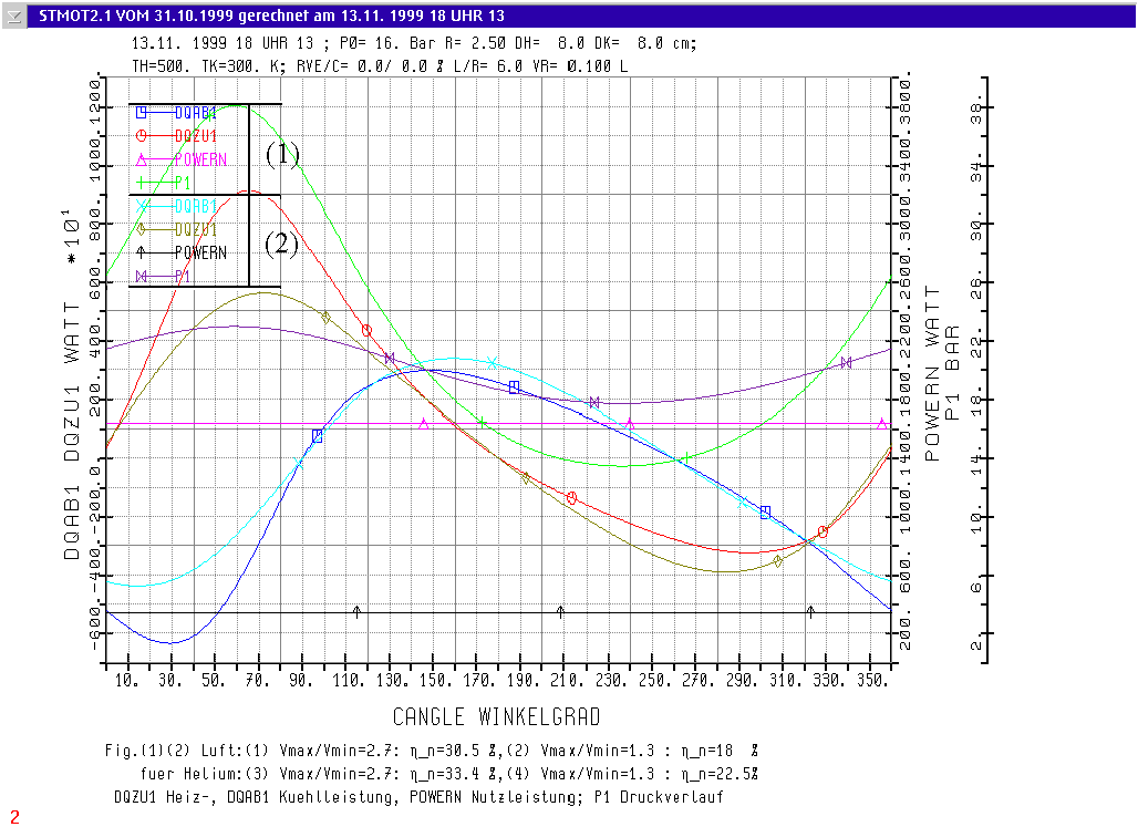
press Your browsers Return button to return into previous text
-
Fig.(5)(6) The Influence of volumeratio V max / V min, the Regenerator efficiency hreg and the idle pressure P0 to the usable Power "POWERN" of the engine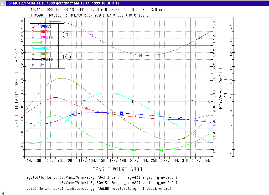
press Your browsers Return button to return into previous text
-
Fig.(5)(6)TS T-S diagrams for air: Run (5) with high volume ratio Vmax/Vmin =2.71 and run (6) with low volume ratio Vmax/Vmin 1.29; the "frames" are equal to the ideal Stirling process. Simulation results see in table at RUN NO. 5 and 6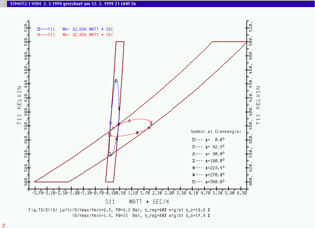
press Your browsers Return button to return into previous text
-
Fig.(7)(8)TS T-S diagrams for Helium: Run (7) with high volume ratio Vmax/Vmin = 2.71 and run (8) with low volume ratio Vmax/Vmin = 1.29; the "frames" are equal to the ideal Stirling process. Simulation results see in table at RUN NO. 7 and 8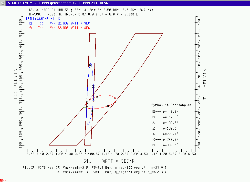
press Your browsers Return button to return into previous text