| HOME | PREVIOUS | NEXT |
The block diagram editor can be used to enter modules and interface ports besides providing pictorial
view of a design.
You can maximize the block diagram view by invoking ![]() Maximize Block Diagram(Ctrl+F).
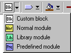
Using the dropdown toolbar as shown below to insert modules in the block diagram.
Select one of the choices, then point to the desired location, left click to place a new block, and
drag the mouse to size the block. "Custom block" is for drawing purpose only. It does not affect the
VHDL coding. "Normal module" is for inserting a new design module. "Library module" and "Predefined
module" are for inserting modules from libraries. After inserting a module, double click or hit
Enter key to name the module. For "Library module" and "Predefined module",
a library browser will be popped up for choosing module to insert.
Maximize Block Diagram(Ctrl+F).
Using the dropdown toolbar as shown below to insert modules in the block diagram.
Select one of the choices, then point to the desired location, left click to place a new block, and
drag the mouse to size the block. "Custom block" is for drawing purpose only. It does not affect the
VHDL coding. "Normal module" is for inserting a new design module. "Library module" and "Predefined
module" are for inserting modules from libraries. After inserting a module, double click or hit
Enter key to name the module. For "Library module" and "Predefined module",
a library browser will be popped up for choosing module to insert.

Select ![]() Library module (Ctrl+Alt+L) from dropdown toolbar
and place it in the block diagram. Double click on it to invoke the library browser, select "Counter"
from the "Basic" library group.
Library module (Ctrl+Alt+L) from dropdown toolbar
and place it in the block diagram. Double click on it to invoke the library browser, select "Counter"
from the "Basic" library group.
Similar to inserting blocks, interface ports are inserted in the same way using the dropdown toolbar as shown below. "Text" is for drawing purpose only. The others are for inserting various modes of interface port. These ports and text are interchangeable by selecting an existing port or text, then choosing a new type from the toolbar. While inserting a new interface port at the block diagram, the interface port is automatically added to the interface port editor. You need to fill in the "Data Type" and "Range" columns to complete the declaration of a port.

Refer to the following block diagram, insert the interface ports accordingly.

Using the interface port editor to fill in the "Data Type" and "Range" columns by
referring to the following figure. Rearrange the sequence accordingly by using the following move
functions:

Lines can be drawn to link between blocks and interface ports. Simple lines can be drawn by using
![]() Automatic Link
(Ctrl+A). After invoking the function, point the mouse to the first block,
drag it to the second block and release, a new line is created. To change the line shape, invoke
Automatic Link
(Ctrl+A). After invoking the function, point the mouse to the first block,
drag it to the second block and release, a new line is created. To change the line shape, invoke
![]() Line Style
(Ctrl+Alt+Enter) repeatedly to choose among several choices. To draw
complex line, another function is used --
Line Style
(Ctrl+Alt+Enter) repeatedly to choose among several choices. To draw
complex line, another function is used -- ![]() Manual Link (Ctrl+M). The function let user to
draw line manually in any shape. Invoke manual link, then point the mouse to a block side, left click to
draw the first point, then click on the desired line path until reaching the second block.
Line thickness, color, and end arrows can be adjusted by using dropdown toolbar. Explore the functions
yourself to get used of it.
Manual Link (Ctrl+M). The function let user to
draw line manually in any shape. Invoke manual link, then point the mouse to a block side, left click to
draw the first point, then click on the desired line path until reaching the second block.
Line thickness, color, and end arrows can be adjusted by using dropdown toolbar. Explore the functions
yourself to get used of it.
In the current version of the VHDLMG (Version 1.08), line drawing in the block diagram does not affect the VHDL coding, which means it has no physical meaning but for visual and documentation purposes only.
Refer to the given block diagram above, complete the block diagram drawing.
| HOME | PREVIOUS | NEXT |