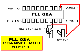
1)Cut the Trace going to PIN #11.
2)Solder a 3.3 K resistor across the cut.
3)Solder 1 leg of a SPST switch to PIN #8.
4)Solder the other leg to PIN #11.
1 - 26.805 . . . . . . . 4 - 26.845 . . . . . . . 7 - 26.875
2 - 26.815 . . . . . . . 5 - 26.855 . . . . . . . 8 - 26.895
3 - 26.825 . . . . . . . 6 - 26.865 . . . . . . . 9 - 26.905

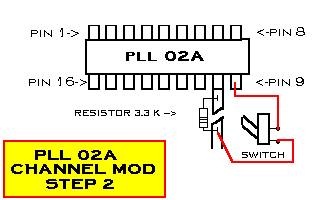
1)Cut the Trace going to PIN #10.
2)Solder a 3.3 K resistor across the cut.
3)Solder 1 leg of a SPST switch to PIN #9.
4)Solder the other leg to PIN #10 after the resistor.
This will give you 26.645 to 26.745 Mhz on channels 1 - 38.

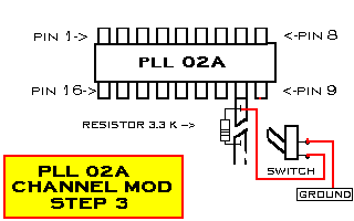
1)Cut the Trace going to PIN #10.
2)Solder a 3.3 K resistor across the cut.
3)Solder 1 leg of a SPST switch to GROUND.
4)Solder the other leg to PIN #10 before the resistor.
This will give you 27.425 to 27.705 Mhz on channels 12 - 38.

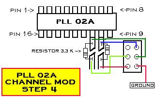
1)Cut the Traces going to PIN #10 and PIN #9.
2)Solder a 3.3 K resistor across the cuts.
3)Using a DPDT Center-Off type switch solder wires from the PLL to the back of the switch as shown.
When the switch is UP.
This will give you 26.435 to 26.7455 Mhz on channels 10 - 38 .
When the switch is DOWN.
This will give you 26.755 to 27.055 Mhz on channels 10 - 38 .


Please report any viewing troubles.
Comments or suggestions regarding these Web pages are welcome.
Email Webmaster.


