Construction Guide
Hints and tips for the VSPS and Phonoclone projects.
If you havent already done so, please read the Phonoclone or VSPS project pages now. Once you are familier with the circuits, have a look at the different layouts of the circuit boards. Together these give you all the information you will need for assembling a parts list. This construction guide aims to explain how to put everything together.

Sourcing the Parts
General components can be bought from Digikey. Hi-fi components can be found at Parts Connexion.
Unfortunately the Black Gate N 4.7 µF / 50 V non-polar electrolytic used for C3 is no longer avaliable. Some boards will accomodate larger film capacitors, in which case 1 µF or 2.2 µF may be substituted, but other boards only have space for an electrolytic. Other options include Nichicon audio-grade non-polar electrolytic or two Black Gate NX 1 µF / 50 V in parallel.
For the RIAA capacitors C1 and C2, I prefer silver mica. Alternatively polystyrene or high quality polypropylene film and foil may be substituted. If possible hand-pick matched values that are as close as possible to those listed on the project page.
I usually use Nichicon Muse(FW) for the filter capacitors in the voltage regulation circuitry, but generic low impedance types types such as Nichicon KMG, Panasonic FC may be substituted. The particular brand or type is not critical.
Some boards will only accept 7 mm resistors, others will take 9 mm or even 12 mm sizes. Please confirm in advance or modify the board to match the resistors you intend to use. Although I've used Riken Ohm for the critical parts in the Phonoclone (R1-4) I can't say for sure that they sound better. Normally I just use generic 1/4 W Takman carbon film types, carefully matching the RIAA values between channels. I try and discourage people from using cheap metal film types. The op-amp circuits seem to be sensitive to high inductance resistors, especially in the feedback loop. Carbon composition resistors can be used, especially for the 47 ohm resistor on the output, but try to refrain for using these for the noise-critical input components (R1-4 in the Phonoclone, R2 in the VSPS).
Soldering the Circuit Board
A couple of tips for stuffing the PCB: Soldering components to a PCB is a little harder than doing point-to-point. Since the components are usually snug to the PCB that leaves precious little lead length between the component on one side and you soldering on the other. Smoking the components is a real risk. I found the following recipe works for me: place the component snug to the PCB, and bend the leads on the opposite side of the board out slightly to hold it in place. Place the soldering iron tip on the pad first for a second or two to heat that up before moving the tip slightly so it contacts both the pad and the lead wire. Wait a further couple of seconds to get the wire locally hot before applying the solder. Of course getting the timing right is, well, a matter of practice.
All the components can be placed on the top, print, side of the PCB.
The op-amps can be used with sockets or soldered directly to the pcb. The order in which to solder in the components are,
- Sockets and pins. Here, sockets if using.
- Resistors. Low power ones first, these are snug to the board. High power ones second, these are positionned with 2 mm - 3 mm of clearance above the PCB. No high power resistors are used on the VSPS PCB.
- Capacitors. Film types first, electrolytics second, smallest to biggest. Check and double check polarity.
- Op-amps and regulators. Check and double check polarity. If the op-amps are socketed, leave putting them in until last.
- Connection wires.
Hooking Things Up
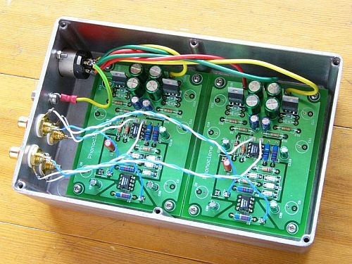
Mounting: There are mounting holes at each corner of the board, 3.3 mm in diameter. The board is attached to the case by standoffs and either M3 or 4-40 machine screws.
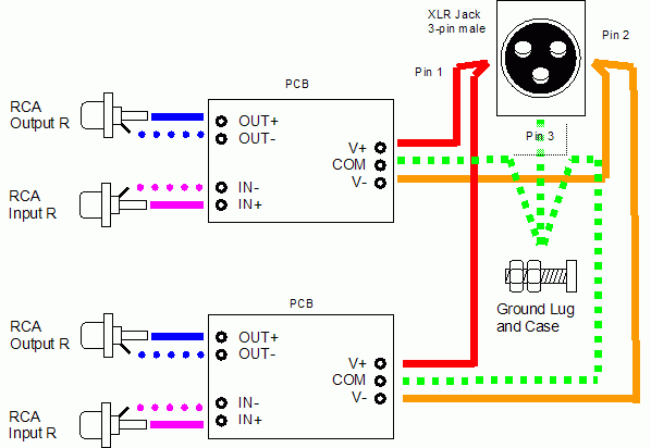
Connections: IN+ and IN- go directly to insulated RCA jacks. OUT+ and OUT- (or O+ and O-) connect to an insulated output RCA jacks. V+ and V- go to the power supply. The COM pad of each board is connected to the case, and then to the power supply or power supplies. The turntable ground is connected to the case. The most common mistake is to not use insulated RCA jacks, the second most common is to somehow forget to connect COM to the case and turntable ground lug.

Fig 1. Connection schematic of the amplifier chassis.
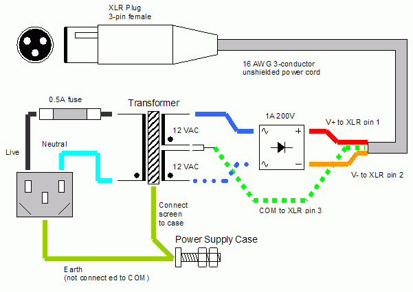
The external power supply is simply a transformer and rectifier. Although the power supply can be in the same case as the phono stage, I recommend that two chassis be used, with the power connection made through a three wire umbilical cable.

Fig 2. Connection schematic of the power supply chassis. The power umbilical is captive on the power supply side.
The main mistake that happens here is people insist on connecting COM to the case. Don't! The only things that connect to this case is the power line Earth wire and the screen tap of the transformer, if the transformer has an electrostatic screen.
Please consult the VSPS and Phonoclone Help Desk at diyaudio.com for additional help and discussion, together with many photos of completed projects.
rjm003.geo at yahoo.com

|