Printed Circuit Boards for RJM Audio Projects
Download layout and schematic files.
General Information : The Boards : Help and Instructions : FAQ (please read!)
General Information
Printed circuit board layouts and schematics are available for the Phonoclone and VSPS projects. You will need to download and install the free Eagle Layout Editor software to view the files. The part numbers are consistent with the project pages. The various circuit boards are differentiated by the size and layout of the board and the configuration of the voltage regulation circuitry.
I do not currently sell these PCBs, you will have to arrange to have them made for you. I am just providing suggested layouts. You can edit the files to your liking and then export the board layout to the Gerber file format before sending the result out for fabrication. You can also generate a bitmap of the traces for etching at home. Perhaps the most convenient service for the beginner though is provided by Olimex. They accept submissions of the Eagle layout files (.brd extension) directly, and will properly process the file for you before fabricating the boards. I have always ordered the boards from Olimex with good results, and can recommend them.
You can do whatever you like with these files, modify them and so forth, except for two things: don't pass them off as your own work, and don't use them for commercial gain.
Circuit Boards
VSPS Basic
The VSPS Basic board is 5 cm x 8 cm, and accepts a dual op-amp of your choice.
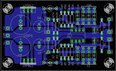
Download schematic and layout files.
Recommended values for voltage regulation components: LM7812, LM7912; C4,C5=1000 µF C6,C7=220 µF. Panasonic FC. In input capacitor CO is optional, set according to the recommendation of the cartridge manufacturer.
Phonoclone R.C.
The Phonoclone RC board is 5 cm x 8 cm. Both op-amps can be isolated from the voltage regulator by an optional RC filter stage.
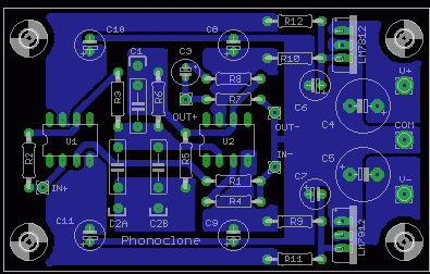
Download schematic and layout files.
Recommended values for voltage regulation components: LM78xx, LM79xx, (10 V versions recommended, 9 V or 12 V also OK); C4, C5 = 1000 µF C8-11 = 100 µF, R9-12 = 10 ohms. For the original (not RC filtered) version simply substitute a section of wire or zero ohm jumper for R9-12.
Phonoclone B.E.
The Phonoclone BE is 10 cm x 8 cm, and takes two single op-amps such as the OP27. It is a dual-layer board with LM317 and LM337 adjustable voltage regulators, a ground plane, an isolated signal shield plane, optional protection diodes, and multiple options for the placement of bypass capacitors.
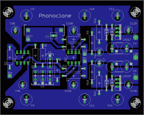
Download schematic and layout files.
Recommended values for voltage regulation components: LM337, LM317, C4,C5=470 µF C6-7=100 µF, C8-13 and C8B-C13B= user configured, 100 µF in C8B, C9B, C10B and C11B recommended. R9, R10 = 1.5k ohms, R11, R12 = 220 ohms. [Vout=1.25(1+R9/R11)]
Phonoclone 3.
The Phonoclone 3 is 10 cm x 8 cm, and is a drop in replacement for the earlier B.E. board. It is a dual layer board and features the Xreg voltage stabilizer circuit instead of the normal 3-pin voltage regulators.
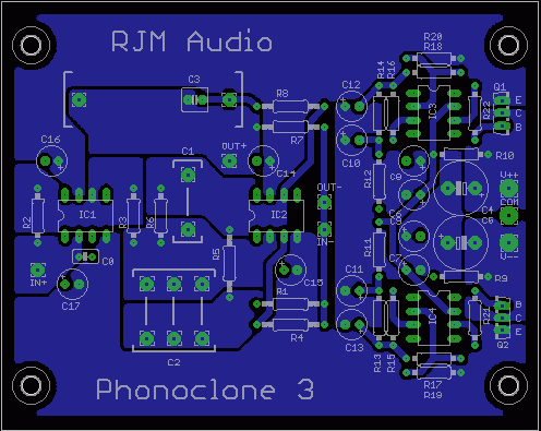
Download schematic and layout files. [Now with parts list and instructions!]
You can also download a sample of Leonard Cohen as heard through my Phonoclone 3. (16 bit 44.1 kHz .wav format, filesize 30 MB)
The most recent news and developments can be found at the Phonoclone 3 thread on the diyAudio forums.
Notes
The Eagle schematic files are not guarenteed to have the correct parts valuesl listed. The definitive, most up-to-date values are always listed on the main project pages, or, for the Phonoclone 3, in a separate list included with the Eagle schematic files above.
Help and Instructions
- VSPS main page.
- Phonoclone main page.
- The construction guide.
- The VSPS and Phonoclone Help Desk at diyaudio.com.
FAQ
- Q. How experienced do I have to be?
- A. The less experienced you are the more risk there is that things won't go well. If you are comfortable with that and have read this far, go for it...
- Q. Why can't I order from you anymore?
- A. I don't have time to be doing this on a weekly or even monthly basis. Ordering from Olimex directly is simpler and faster, with no significant difference in price.
- Q. How much will it cost?
- A. From Olimex, about $40 US including shipping. There is the minimum order of one 10x16 cm substrate. This will give you four 5x8 cm boards, or two 10x8 cm boards.
- Q. Is there a printed instruction manual?
- A. No. There is a building guide online, see above. Please read this carefully first, then try the VSPS and Phonoclone Help Desk thread at DIY Audio. Links to these resources can be found above.
rjm003.geo at yahoo.com
|
|
|
|
|
|
|