The Xreg Voltage Stabilizer
A low noise, high bandwidth voltage regulator for audio circuits.
Introduction
Spend any amount of time trying to optimize op amp circuits to sound their best and sooner or later you'll find yourself looking to upgrade the voltage regulators. From the LM78xx series to to the adjustable LM317 to perhaps the LT1086. The DIY audio approach to regulators, as defined by the Sulzer, Boberly and Jung circuits, is nicely summarized in this review by Tangent. The main advantage of these circuits vs. a typical integrated package like the LM7812 is that the component parts of the regulator are separated and optimized individually. A high end op amp is chosen for error amplifier, for example, and a low noise, filtered voltage reference is used. The fundamental topology remains essentially unchanged however. More (a lot more) on voltage regulators for audio at Walt Jung's site, here.
The Xreg is different because it is designed from the outset around a split voltage supply, having both positive and negative rails. The single supply, non-inverting error amplifier common to almost all regulator designs is replaced by an inverting gain stage operated from split supplies. The reference voltage must therefore be of opposite polarity to the output voltage: the positive output takes the reference generated by the negative input voltage and vice versa. It's from this crosslink, which make an "X" on the PCB trace, that the Xreg takes it's name. The circuit only makes sense if both positive and negative regulated voltages are required of course. It's also limited to relatively low output voltages, in practice up to about ±12 V. It is intended for use with low voltage, low current audio circuits such as solid state phono stages, preamps, and headphone amplifiers.
How it Works
The essence of the tranditional series voltage regulator is shown in the following diagram. It comprises an amplifier, a pass transistor, and a couple of resistors:
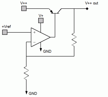
The traditional series regulator circuit is supplied by three voltages, the high current, raw input voltage that is going to be regulated, V++, a low current, filtered voltage for the regulator circuitry itself, V+, and a stable, very low noise reference voltage, +Vref. (In integrated regulators both high and low current circuits are supplied by V++, and the reference is generated internally.) The error amplifier reacts to keep the output voltage, V++ out, a constant multiple of the reference. A negative regulator, which is generally needed in addition to the positive regulator for op amp audio circuits, has the same basic topology but requires three additional supply voltages; V--, V-, and the negative reference -Vref. The Xreg design came out of the realization that the both positive and negative regulator circuits would benefit from sharing those six voltages between them, rather than using only the three with the same polarity as the output.
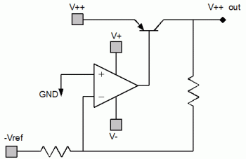
The positive side of the Xreg regulator uses V++, V+, V- and the negatve reference, -Vref:
In the negative half of the Xreg, which uses V--, V+, V- and Vref, the NPN pass transistor is replaced by it's PNP equivalent:
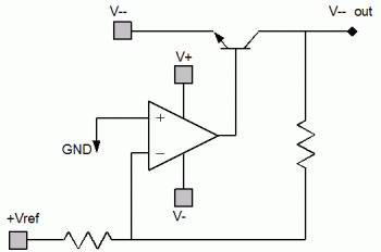
The first thing to note is the op amps are operated from split supplies. This provides the genuine benefit of doing away with the virtual ground. Since the op amp can now handle both positive and negative inputs and outputs we can additionally reconfigure the op amp as an inverting stage and keep the non-inverting terminal grounded. The inverting topology is the "native" state of an op amp, and offers several advatanges, stability being perhaps the most important. The inverting stage requires a reference voltage of the opposite polarity as the output, this reference is simply "borrowed" from the other half of the circuit.
That covers the topology innovations. The final element of the Xreg that needs explanation is the voltage reference. Rather than use a Zener or bandgap reference, which are noisy relative to passive components, a simple voltage divider is used in combination with heavy filtering. It's basically a big RC filter, actually implemented as a multi-stage RCRC network attached to V+ or V-. Most of the supply noise is attenuated below the noise floor of the op amp, but in order to achieve this level of filtering the reference voltage ends up quite small, only a few hundred millivolts. The gain of the inverting stage must therefore be set quite high to compensate, serving to naturally roll of the response at around 300 kHz and, it is hoped, making the regulator relatively stable in the process. A side benefit of the voltage-divider-as-reference is it automatically soft-starts the regulator over a period of a few seconds, eliminating turn on thuds and limiting inrush currents through the pass transistors.
Of course the reference voltage is not an absolute value, but rather defined as a fraction of the input voltage V+ or V-. If the line voltage fluctuates on a time scale longer than the time constant of the filter - as typically implemented, 10 seconds or so - the output voltage will gradually follow in proportion. It behaves as an unregulated power supply in this regard, and the Xreg is therefore more accurately called a voltage stablizer or a line smoother than a voltage regulator. I generally still refer to it a regulator because the Xreg replaces, and serves the function of, the voltage regulators in providing low noise, low output impedance voltage rails.
Evaluation Circuit and Printed Circuit Boards
The Xreg circuit is normally an integral part of the circuit it powers, and usually placed on the same circuit board. Component values are chosen to suit the particular application. The first application of the Xreg was the Phonoclone 3 project, where it was combined with the Phonoclone MC phonostage to good effect. Please download the latest revision of the schematic and layout files of the Phonoclone 3 from the RJM Audio products page if interested.
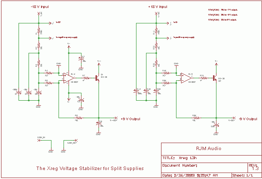
For general purpose use, a standalone evaluation circuit is presented below that will output about ±9-12 V rails from ±18 V DC inputs. It is intended to be paired with a transformer with 12 VAC secondaries. (The VSPS or Phonoclone power supplies, for example.) The output voltage can be set by changing the value of R2, R2A and/or R3, R3A. An excel worksheet is provided to facilitate resistor selection. If more than 200 mA output current is required, the pass transistors should be heatsinked.
The evaluation board is single-sided board and measures 5x8 cm. It can be used for testing, or retrofitted to upgrade existing equipment.
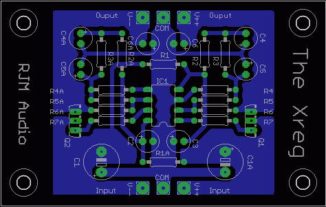
Download schematic and layout files. (In Eagle format.)
The circuit schematic is as follows: (click for a larger view)
Considerable care went in choosing the capacitance values to ensure that the reference and op amp sections do not add ripple or undue noise to the output. There is little to be gained from increasing them further. As implemented in the Phonoclone 3, the Xreg works, and works well, in its stated goal of significantly improving the sound of op amp audio circuits.
rjm003.geo at yahoo.com

|
