Technical |
||
| HOME BOX 1 TECHNICAL |
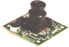
Each nesting box is fitted with a small ccd video camera. The camera has a built in microphone so we can hear what is going on as well. We have mounted the cameras in small plastic housings along with 4 infra-red light emitting diodes. These cameras are usually used for security systems but can easily be adapted for other purposes. The pictures are only black and white because the camera has to be able to see in the 'dark'. In fact, it is not really 'dark' because the inside of the nesting box is lit by infra-red light which the camera can see. Like us, the birds cannot see the infra-red light so are not disturbed by it. The output from the cameras can be connected directly to a standard television, video recorder or a tv/video card in a PC. For the pictures on these web pages we are using a video capture card in the PC to take snapshots of the activity. Details of camera and parts list. The following shows how the camera is put together but does not give full construction details.
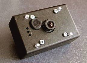
Picture 1 shows the completed camera. The four screws you can see hold the metal posts that support the camera circuit board. To give you some idea of scale, the distance between these screws is 32mm. Just outside the screws you can see the four plastic lenses that cover the infra-red LEDs. These lenses just snap into holes drilled through the plastic box. The microphone is held in place by a rubber grommet just to the left of the camera lens. The three small holes have been made to allow air circulation through the camera box.
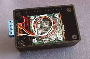
Picture 2 shows the camera with the back removed from the plastic box. You can see the four screws that attach the camera circuit board to the metal mounting posts. The blue terminal block on the left hand side is soldered to a small piece of veroboard which is inserted through a slot cut into the plastic box.
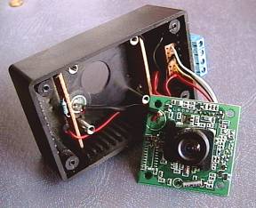
Picture 3 shows the camera circuit board removed from the mounting posts. You can see the two small pieces of veroboard that have the infra-red LEDs and resistors soldered to them. These are held in place by the slots that are part of the plastic box and also by clipping the LEDs into the plastic lenses that are fixed into holes in the front of the box. You can also see the microphone that is fixed into the front of the box by a rubber grommet. This was removed from the camera circuit board and re-attached using a short length of cable. This was done to try to improve the sound quality.
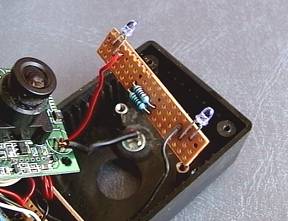
Picture 4 shows one of the small pieces of veroboard with two of the LEDs and the resistors that are used to drop the voltage for them. The resistors run fairly hot which is one of the reasons for making the small ventilation holes in the plastic box. One benefit of this heat is to keep the camera box free from condensation :-) Parts list
Construction could be simplified by not removing the microphone from the camera module. This bit is tricky as it is soldered on to the very tightly packed circuit board. Fitting the grommet and the microphone to the front of the plastic box is also a bit fiddly. Fitting the terminal block is also a bit fiddly but once done this provides a very easy method of installing and removing the camera. If you use an alternative camera, make sure that the lens can be adjusted. Most cameras will be supplied with the focussing set from infinity down to about one metre. Obviously for the bird box this will need adjusting so that it can focus down to just a few centimetres.
|
|
|
If you have any comments about these pages please feel free to contact us at staughton@email.com First released on 28 March 1998 and updated on 23 March 2001 |
||
