|
|
Fuzzy
logic controllers
Wide range of opportunities is
opened in the field of digitally controlled systems by
microcomputer development. Digitally measured informations are
rapidly processed. Complex systems are easily controlled.
The diversity of controlling software allows more creativity to
experts. New approach in controlling was introduced, using the
fuzzy regulators. The expert, familiar with the certain process,
easily can implement the solution, by simply writing and
changing the program code.
Before the microcomputers appeared, the automatic process
control and machine control was based on analog regulators.
Digital control algorithms are slower then the analog ones.
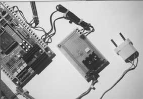
Experiment system detail
Flexibility in control realization and modifications are easy
using software, simply changing the code. New methods of control
are introduced. In many different conditions, these prove to be
very efficient. A specific application: neural networks and
fuzzy logic use on system control.
Digital
Controlling
Digital
control offers opportunities for new modalities, that analog
regulators were not able to offer (or are difficult to
implement): data acquisition, system identification, adaptive
control etc. (terms known from the theory of digital
controlling). Two important terms are connected with digital
systems: discretisation by time (sampling time) and quantisation
by level. The sample rate defines successive moments in which
sampling of continual values is being performed. As a result of
AD conversion, quatisation of continual values appear.
Intelligent control application can be understood on the need of
performing a regulation of a physical dimension in next
circumstances:
1. On real systems, different disturbances influence
constantly
2. Real processes, in most of the cases are nonlinear
3. The processes are changeable
The outlined demands often are met in daily life. Intelligent
controlling is thus necessary.
FLC Designing phases
Fuzzy Logic Controllers (FLC) are an example of such kind of
controlling. Convenient for the systems that are hardly modeled.
These are the phases of designing the Fuzzy regulators:
1. Process analysis
2. Rule determination, by an expert
3. Simulation of the Fuzzy regulator. If we do not receive
the desired results, we have to repeat the steps.
The realization of FLC in a digital control system consists
in source code writing (we used the C language in our example).
Based on given temperature, the regulator reaches the desired
value and maintains it, until a demand for another value
appears, given by the user. Before starting to write the program
code, analysis (and surveillance) on the specific control system
is necessary It is desirable to describe the system
mathematically, to simulate the process using a microcontroller
and then to implement the program. The purpose of the simulation
is: using mathematical algorithms we try to describe the
happenings in a real system. This way we can verify if the
control algorithm fulfills the demands in reality. Usually,
initial conditions are given, in time domain. The advantages of
such systems are to insure stability, precision and speed.
Fuzzy Logic
In the classical theory of
groups, we say that a certain element belongs or does not belong
to the appropriate group.
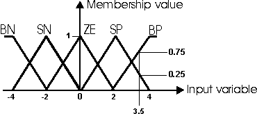
Picture 1. Belonging function
The experiment -
water temperature regulation. The water can be hot or cold. Such
approach is simplification of real situation. In this example,
the graduations of temperature are neglected. This approach is
thus unprecise. In everyday life, we can hear terms like, little
bit colder, little bit warmer, cold, hot, very hot, etc. One
solution is to introduce terms like in the picture 1, : Very
Negative, Little Negative, Around Zero, Little Positive, and
Very Positive (VN, LN, AZ, LP, VP). The fuzzy logic theory was
introduced for this kind of representation. Lotfi Zadeh was its
inventor. A value can belong to different representations, this
way its description becomes uncertain, fuzzy. For instance, the
fuzzy value F=3.5 is LP with belonging degree n=0.25 and VP with
n=0.75.
Expert Systems
Fuzzy logic usually is associated with expert systems. In
these, the actions perform in real life by experts, can be used
for programming computer systems that later can imitate or
perform the job of experts. Manual control involves man's
intelligent action of monitoring and controlling the
certain process. With this approach, we can accomplish good
control, because the expert knows how to guide the system. In
order to write a program for FLC, it is necessary to introduce a
group of fuzzy rules. The rules describe the expert's action.
The situation in the control system can be described as next:
the expert monitors the system (example: the deviation of
temperature value from the given, initial, temperature) and
decides how much to warm up the water.
Fuzzy rules
In expert systems, the knowledge of the expert is described
the next way: IF the mistake has this value THEN heat for that
value long time. In most of the programming languages, it can be
implemented with IF THEN rule. The next situation shows an
example of control: water is heated. At the start it has the
room temperature, lets say about 22 C degrees centigrade and has
to be heated to 40 C. An "average" expert will
probably react the next way: lets heat the water until it
reaches the 40 C, then, we will maintain the temperature to
40 C, on the principle of work of an ON/OFF regulator. Instead
of using a classical ON/OFF, we often use the ON/OFF
regulator with hysteresis. This means the temperature is
maintained in certain intervals, for instance between 39 C and
41 C. The question of quality of this way of control depends on
the demands of the buyer, that orders the system (temperature
regulator). First, it is useful to notice that the temperature
is oscillating between 39 and 41 C. The second, if in the system
exists a noticeable delay (the energy of the heater is not
instantly transferred) it is logical to expect that in
temperature reaching, there will be an overstepping of the value
of 41 C (the higher delay, the higher temperature) and the
interval (39, 41 C) is expanding.

Picture 2. Control system structure
In case of ON/OFF
regulator, in fuzzy logic, the temperature regulation will be
implemented the next way :
IF temperature < 39 C THEN heater ON
IF temperature > 41 C THEN heater OFF
This regulator can be easily implemented both in software or
hardware environment (digital or analog control respectively)
and it is pretty simple. We have to be aware that there also
exist groups of rules that describe the temperature regulation
more precisely, in this system.
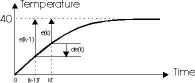
Picture 3. Error and error change
Bart Kosko showed
theoretically that the Boolean algebra (1 or 0) is only a
special case of fuzzy logic, actually its subgroup. The ON/OFF
regulator is only a special case of FLC. FLC should be
considered as an algorithm that based on two values (error and
error change) calculates the control. It means how much (inside
a period T=4 seconds) to heat, to achieve the desired
temperature (Picture 5).

Picture 4. Fuzzy logic controller
structure
The error (given
value - instant value) gives the information how much the
instant temperature is away from the given one. The error change
(instant error - previous error) gives the information about the
speed of achieving the given value (Picture 3). These two values
are the input in FLC and they have specific values (in C).
Achieving the real value of control
The data processing of the achieved information is performed
in next 3 phases:
1 . Scaling
2 . Look-up table (calculating the fuzzy control)
3 . Inverse scaling

Picture 5. PWM signal
Scaling: The error
and the error change are scaled. For instance, if the given
value is 40 C, and the instant value is 30 C then the error is
e=10 C. If the previous error value was 28 C, then de=2 C. These
values are sampled in k*T moments and k is an integer. The
error and error change are recalculated into fuzzy variables
ef and def. The fuzzy values are supposed to be in the interval
between -4 and 4. To these values an interval of real numbers is
attached (e and de). On the basis of given value and starting
(initial) temperature value, we determine the emin and emax. For
instance, if the given temperature value is 40C and starting
(initial) value is 10 C, we calculate the emin = - 30C and emax
= 30C. We presume that during 4 sec, the temperature can
maximally rise for 1 C; it comes out that demin = - 1 C and
demax = 1 C.
LOOK UP TABLE:
(calculating the fuzzy control). When we want to determine the
ef and def, on the basis of the Look_up table we determine the
uf (fuzzy control).
| ef\def |
-4 |
-3 |
-2 |
-1 |
0 |
1 |
2 |
3 |
4 |
| -4 |
0 |
0 |
0 |
0 |
0 |
0 |
0 |
0 |
0 |
| -3 |
0 |
0 |
0 |
0 |
0 |
0 |
0 |
0 |
0 |
| -2 |
0 |
0 |
0 |
0 |
0 |
0 |
0 |
0 |
0 |
| -1 |
0 |
0 |
0 |
0 |
0 |
0 |
0 |
0 |
0 |
| 0 |
0 |
0 |
0 |
0 |
0 |
0 |
0 |
0 |
0 |
| 1 |
1 |
1 |
1 |
2 |
2 |
2 |
0 |
0 |
0 |
| 2 |
2 |
2 |
2 |
3 |
4 |
4 |
3 |
2 |
2 |
| 3 |
3 |
3 |
3 |
3 |
4 |
4 |
4 |
4 |
4 |
| 4 |
4 |
4 |
4 |
4 |
4 |
4 |
4 |
4 |
4 |
Look-up table
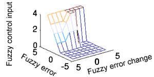
Picture 6. 3D projection
of Look-up table
Descaling: Control in real time, demands the translation of
fuzzy control into real value. As the period is T=4 sec, the
control determines in which area of the interval the heater is
ON. (Picture 5). The control has the shape of PWM signal,
that serves to turn ON and OFF the heater. In the previous
example, the steps of scaling and descaling are pretty simple.
Now we are going to explain the step of creating the LOOK_UP
table, that in fact is the base of the control algorithm itself.
Creating the Look-up table
Before we start to elaborate the creation the Look-up table,
lets imagine we already have one created. Analyzing the Look-up
table, we can notice that control can only be positive. That
means, the system can only be heated. (it cools by turning OFF
the heater). The values of uf are 1,2,3 or 4 that means in the
period of 4 sec the heater is ON for 1,2,3 or 4 sec. We can
notice that fuzzy control is much more precise then the ON/OFF
control. How more precise it is, depends, on the structure of
FLC, on the software. The procedure of achieving the values
(0,1,2,3 and 4) that are described in the Look-up table can be
understood on the basis of a help table usually called Fuzzy
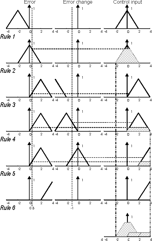
Associative Memory-Picture 7.
1. IF e LN
THEN u AZ
2. IF e AZ
THEN u AZ
3. IF e LP
AND de VN THEN u LP
4. IF e LP
AND de LN THEN u LP
5. IF e LP
AND de AZ THEN u VP
6. IF e VP
THEN u VP
A comment on the rules written above: 1. and 2. do not allow
the temperature to be higher then the given one. The rules 3.
and 4. restrict not to overheat the water if the error is not
too big and there exists a tendency to achieve the given value
of temperature. Rule 5. says, if the error is not too big, but
there does not exist a tendency to achieve the given value, then
we have to heat more intensely (longer). Rule 6. says that for a
big error we have to heat with much greater intensity. In a
certain moment, there exists one fuzzy error (ef) and one fuzzy
error change (def). On the basis of picture 7, we determine the
degree of belonging of ef and def for the first rule. Later we
determine the minimum of these two values, and this way we
achieve the dashed surface. The procedure has to be repeated for
all the other rules. The surfaces we get from the calculations
have to be summed, and by one of the methods, we determine the
fuzzy controlling.
Determining the control
For calculating the fuzzy control, it is necessary to
determine the center of gravity, using the shapes determined in
the previous steps. The simplified calculation is based on the
next formula: uf=(F1*n1+...+Fk*k)/(n1+...+nk), k=1 : 6. The
analogy is certain with the calculation of center of gravity in
mechanics. For instance, if ef = 0.5 and def = - 1 then we can
see from Picture 7 that uf=(0*1+2*0.25+4*0.25)/(1+0.25+0.25)=1.
Each pair of values of e and de can be from the domain
(-4,4)X(-4,4). This way, uf can be calculated. For forming
the Look-up table, we need integers-positive and negative
(-4,-3,...,3,4). We enter the so created Look-up table into the
program that is performed by the microcontroller. There,
it is used for real time control. After we described the
procedure of creating the Look-up table, it is useful to try to
find out the possibilities for adjusting the control algorithm,
to determine the parameters upon which the FLC depends:
· Setting up the resolution of fuzzy variables (for fixed
limits of real values). The resolution that we introduced in our
example goes from - 4 to 4. There are no limits
for the values to be (-2,2) or (-10,10). In the first case, less
precise control is chosen, while in the second, we chose a more
precise control.
· The number of labels is 5 (very negative,...,very
positive). This number can be 3 or 7 or 9 etc. The smaller
number of labels supposes smaller precision, while greater
number of labels supposes more precise control.
· The function of belonging can be of different dimensions
and shapes: trapezoidal, Gaussian, triangular etc. In our
example, we used the function of belonging in a shape of
triangle.
· The number of IF...THEN rules is not fixed; it is
determined by the expert.
From the enumerated objections, we can conclude where we can
find ways to make adjustments. The understanding and mastering
of the process is of great importance for good FLC adjustment.
Before a practical use of FLC, it is desirable to perform a
simulation of control on the computer. This way we are able to
test the possible behavior of the process in the procedure of
control. The most commonly used program package for this purpose
is MATLAB.
| |
VN |
LN |
AZ |
LP |
VP |
| VN |
- |
- |
- |
- |
- |
| LN |
AZ |
AZ |
AZ |
AZ |
AZ |
| AZ |
AZ |
AZ |
AZ |
AZ |
AZ |
| LP |
LP |
LP |
VP |
- |
- |
| VP |
VP |
VP |
VP |
VP |
VP |
Table of FAM (Fuzzy
associative memory)
Picture 7. Fuzzy control determination - gravity method
The
description of a real system
The central part of FLC is a board with Motorola's
MC68HC11F1 microcontroller working on 8 MHz. On the board,
behind the controller there are included: 32 Kb of memory, power
regulator 7805, power monitor with reset circuit TL7705, and all
the necessary passive components for work. For indicating the
temperature, a 7-segment display is chosen, with 4 digits.
driven by Motorola's MC14499 circuit.
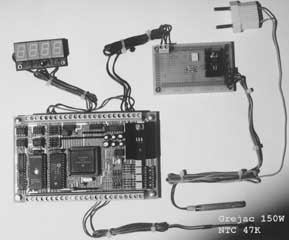
Picture of experimental system
The heater is connected to
the mains, via a tyristor, that is activated by an optocupler
with zero-crossing circuit MOC 3043. The optocupler is connected
to the zero line on port G ( PG0 ), and activates on logical
‘0’. The heater is of 150W. It serves to convert the digital
signal of PWM into the action of water heating. Next to the
heater, in the box, we have an NTC resistor, termomether and
mixer. The mixing is of extreme importance, because it reduces
the delay in the system, and guarantees a linear temperature
distribution. In this case, the temperature difference between
the top and the bottom of the vessel equals 0.2 C. We can
consider it as a very good result. The NTC resistor serves as a
measuring instrument, whose purpose is to give the information
about the instant temperature values.
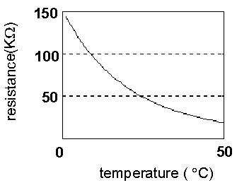
Picture 8. NTC resistor
resistance/temperature dependence
For temperature
measuring, an NTC resistor of 47K, from Simens is used with a
tolerance of 10%. The label NTC (Negative Temperature
Coefficient) describes the nature of the resistor, that in
dependence of temperature change, changes its resistance. The
change can be positive-the resistance increases with temperature
increase and negative-the resistance decreases, with temperature
increase. In this case on 0 C resistance is 165.642K.
On 25 C (that is the referent one) 47K. The label 47K
describes the value of the resistor, on the referent
temperature.
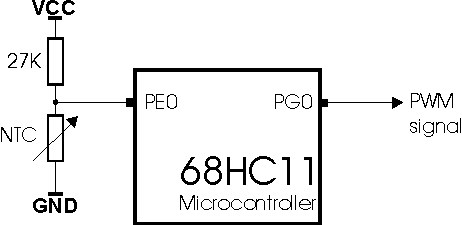
Picture 9. AD conversion and real
control
The resistance
dependence can be also mathematically described the next way:
R=RO exp(b/T). RO is a constant that depends upon the material
and dimensions of the resistor, b is a coefficient of
temperature sensitivity and T is the temperature in (K). With
temperature change, the resistance of NTC changes, and the
voltage with it that is recorded on the AD converter. We
used an internal 8 bit AD converter with precision of
1LSB. For temperature displaying, it is necessary to recalculate
the voltage of NTC into temperature. There are two
possibilities. One is - using the formula, we directly calculate
the temperature. The second one is, to experimentally determine
the table that linearise the real characteristic. In our
example, we used the second method. The labels PE0 and PG0
represent the ports of the microcontroller. For instance, PE0 is
the E port (the input of the AD converter), the zero line. On
the basis of the used components, the maximal accuracy
(precision) that can be achieved is 1 C, that is usual in
temperature measuring. Using higher quality parts and AD
converters, and higher resolution, better results can be
achieved. On the other side, the costs of the entire project
increase.
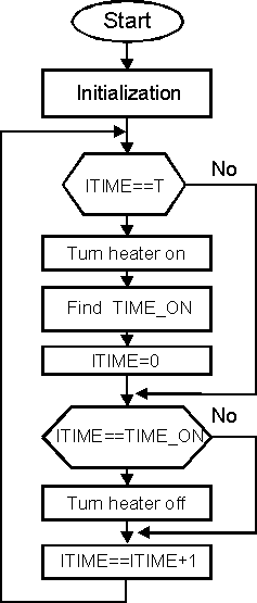
Picture 10. Program execution diagram
The procedure of control is the next: the referent value is
given, and in periodical time intervals (sampling rate is 4 sec)
a digitalized information of the instant value of temperature is
acquired. After that, we calculate the error and error change.
Using these (previously scaled) from the Look-up table, we read
the scaled value of control (from 0 to 4) that after this are
descaled and as such, represent the interval during which
the heater is turned ON. The job of the microcontroller is to
insure that the heater will be ON as long as it is calculated.
On Picture 10, a block diagram of the described control
system is shown.
|
unsigned
char LOOK_UP[9][9]={{0, 0, 0, 0, 0, 0, 0, 0, 0 },
- {0, 0, 0,
0, 0, 0, 0, 0, 0 },
- {0, 0, 0,
0, 0, 0, 0, 0, 0 },
- {0, 0, 0,
0, 0, 0, 0, 0, 0 },
- {0, 0, 0,
0, 0, 0, 0, 0, 0 },
- {1, 1, 1,
2, 2, 2, 2, 2, 1 },
- {2, 2, 2,
3, 4, 4, 3, 4, 4 },
- {3, 3, 3,
3, 4, 4, 4, 4, 4 },
- {4, 4, 4,
4, 4, 4, 4, 4, 4 }};
- unsigned
char REF,TEMP, ERRMAX,DERRMAX, FUPR;
- unsigned
int ITIME, TIME_ON,T, PRIV;
- unsigned
char C1,C2,ISPISI,UPRMAX;
- signed
char ERR,ERR2,FERR,DERR,FDERR;
|
Listing 1.
Program fazi1.c
|
static void
interrupt intr(void)
- {
- ITIME=ITIME+1;
- ADCTL=0;
- do{}while(ADCTL
!=0x80);
- PRIV=PRIV+ADR1;
- if(ITIME==T)
- {
- if(TIME_ON!=0)
PORTG=0; /* T=4s*/
- PRIV=PRIV/244;
- TEMP=(unsigned
char)(PRIV);
- PRIV=0;
- DERR=(signed
char)(ERR-ERR2); FERR=4*ERR/ERRMAX;
- FDERR=4*DERR/DERRMAX;
- FUPR=LOOK_UP[FERR+4][FDERR+4];
- TIME_ON=FUPR*UPRMAX/4;
- ERR2=ERR;
- ITIME=0;
- }
-
- if (ITIME==TIME_ON)
PORTG=0xFF;
-
- TFLG2=0x40;
- }
|
Listing 2.
Program fazi2.c
|
main()
- {
- PRIV=0;
- ITIME=0;
- REF=114;
- T=244;
- UPRMAX=T;
- TIME_ON=0;
- OPTION=0x80;
- ADCTL=0;
- do{}while(ADCTL
!=0x80);
- ERRMAX=ADR1-REF;
- ERR2=ERRMAX;
- DERRMAX=ERRMAX/5;
- PORTD=0x2F;
- DDRD=0x38;
- SPCR=0x5C;
- DDRG=0xFF;
- PORTG=0xFF;
- PACTL=0x02;
- TMSK2=0x40;
- TFLG2=0x40;
- di();
- set_vector((isr
*)0xFFF0,intr);
- ei();
- for(;;)
- {
- Konvertuj(TEMP);
- Ispisi();
- }
- }
|
Listing 3.
Program fazi3.c
The control algorithm is placed in the interrupt routine, and
activates each 16.384 ms. To adjust the sampling period of 4 s,
we need around 244 RTI interrupts. When the working time of the
heater is calculated (0<TIME_ON<4) it is necessary to
ensure turning OFF of the heater, after the elapsing of the time
interval. This way generating a PWM signal with a 4 s period,
that represents the control. On listing 1, variables used in the
program are declared, and the initialization of the Look-up
table is done. Listing 2 represents RTI ( Real Time
Interrupt) the interrupt routine, in which the results of the AD
conversion are processed and the times of turning ON of the
heater are calculated. In the interval of 4 seconds, the program
enters 244 times the interrupt routine, and each time the value
from the AD converter is red. Their total sum (PRIV) after 4
s elapse, is devided by 244, this way very regular temperature
readings are accomplished. Calculating the medium values, we can
achieve more precise results and we can reduce the influence of
noise. Listing 3 is the main program. In the first part, we
initialize the variables that appear in the program, SPI
communication and RTI interrupt are declared. In the
closed-loop, there are only two functions. The first one
performs the conversion of temperature from binary into decimal
values (necessary for the display) and the second function sends
the decimal ciphers of the instant temperature values trough SPI
communications.
Comments on Results
Before the implementation of the control algorithm on a
system, we performed a simulation. The simulation is performed
on the bases of the law of energy transformation. The
transformation of electrical energy into heat can be described
with next equation: P*dt=m*c*dT. P=150W, heater power, dt is the
heater working time, m=0.4 kg mass of water, c=4186J/Kg*K,
specific heat capacity of water and dT is the change of water
temperature as a result of heating. After the simulation, the
control algorithm is tested on a real system. Each 4 sec the
values red from the AD converter are stored in the external RAM
and after that, this value is transferred by serial
communication to the computer, where the data are processed.
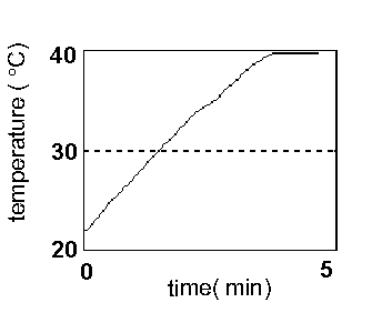
Picture 11.simulated results of the
system with Look-up table
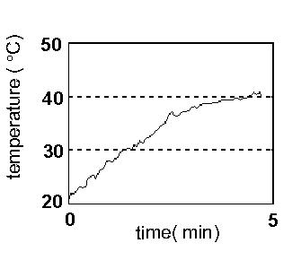
Picture 12.real results of the
system
Comparing the simulated and achieved real results of the system,
we can notice a large degree of similarity. The difference
between the simulated and real system, appears as a result of
noise in the system, and as the impossibility to simulate the
entire real system completely. Instead of conclusion, we offer
the answer to the question why fuzzy controllers are convenient
for automation engineers? They describe the solution without
complex mathematical model of the system.
· Optimizes the already existing solutions, with the purpose
to achieve a more simple and efficient end product
· Reduces the price of the end product on the bases of
simplified procedure of modeling
· Clarifies the system. System is understandable, easier for
maintenance and upgrading
· Higher resistance to errors and changes of the system
environment
· Increases the system robustness without decreasing its
sensitivity
On the bases of the performed experiments, we can conclude
that fuzzy logic controllers are applicable in the problems of
temperature regulation. We can not give a final mark about the
possibilities and quality, because the system was not tested in
the conditions of disturbances, nor compared with other control
algorithms (from which the PID regulator is the typical
representative).
autors:
Stevan Tošić
dipl. eng. & Nebojša
Matić
translated by:
Simeon
Todoran
|