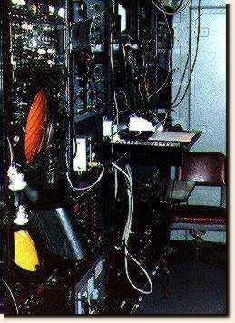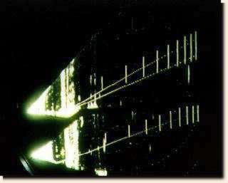
The yellow scope below is the precision approach radar indicator. It had a range of 10 miles and had a peak power of 40 kw. Once the aircraft was identified on the precision radar scope, (photo below), the GCA controller would talk the pilot onto the center line by giving him heading changes. The GCA controller would also tell the pilot if he was above or below the glide slope.
The precision radar display, shown below, shows two different pieces of information. The top half, (two dashed lines), shows the 3.5 deg glide slope, (upper dashed line), extended to ten miles. The short vertical lines are mile markers.
 An aircraft blip can be seen
below the second and third markers from the right edge of the screen. The bottom half of the screen shows the center line of the runway, single dashed
line. The very brights objects to the far left of the screen is ground return clutter.
The all tube, CPN-4 / MPN-11 GCA, radar was used until it was replaced by various all solid state, GCA radars thoughout the Navy and Marine Corps.
Next Equipment
(more to come)
| Awards |
Images and Page design
Copyright © 1997-98 by Bruce T. Janes, B&D Designs. All rights reserved.
Contact me for Graphics Creations. All images contain copyright information.
| This page hosted by
|