|
The increasing of flexibility of the supply in the automated assembling is
subject to many research areas, one of which is the application of
industrial robots equipped with computer vision systems. Such systems afford
high flexibility, but there are still economical and technical obstacles for
their extended application. This investigation aimed at constructing of a
technical vision system in order to increase the flexibility of an
assembling unit served by a robot. The system should also be economically
effective and easy for application.
The possibilities for increasing the flexibility of the
robotized unit were systematized through analyzing the subsystems of the
unit and their share to the flexibility. An assembling unit was chosen from
an available system consisting of a special conveyor, carriers and
industrial robot SCARA. For scene of the computer vision system was chosen
the carrier, which had proper surface, where the assembling details were
recognized.
The basic variants for the position of the technical
vision apparatus were formed. The optimal optical conditions and the
performance of the system were proved through experiments.
The suggested model for increasing the flexibility of the
robotized assembling unit has the following advantages: uniformity of the
equipment not requiring special attachments, small changes in the kinematics
of the position (in finding the proper place of the computer vision system),
possibility for control of the robot hand, possibility for analysis and
qualitative control of the surfaces of the details, possibility for
processing of two- and three-dimensional surfaces, possibility for dynamic
control of the position and relatively cheap components of the whole system.
Some experimental Results
Here I can show you some real object calculated with my
software
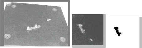
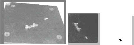
- On the each first picture you can see the object taken with fhree view point
[angle between 30-80 degree from frontal direction].
- Each second picture represents scene (somme part with important for calculation
information with objects). The computer represent this scene with frontal view
point calculating basic picture point by point transforming angle of basic
plane.
- The third picture represents only the objject taken after some filters and
algorithm for separating objects. This algorithm takes objects one by one from
scene giving the best conditions to neuronet to calculate only one object in the
moment. In this way you have a possibilities to calculate many objects in one
scene.
I show you seven objects because the neuronet was trained for this objects.
| Object num. |
Real picture, segmentation and object recognition process |
|
| 1 |
 |
Object 1 is а driving wheel with diameter 9
sm. and scene is 10sm sq. This wheel has altitude 20mm. |
| 2 |
 |
Object 2 The middle picture represents a
special filter (software for plane light intensity regulation) |
| 3 |
 |
Object 3 |
| 4 |
 |
Object 4 This object has light reflection
similar to the background (this is a synthetic material) and it is very
difficult for recognition |
| 5 |
 |
Object 5
|
| 6 |
 |
Object 6 Separate from 2 details |
| 7 |
 |
Object 7
|
|

